
Surgical traction apparatus

a technology of traction apparatus and traction rod, which is applied in the field of surgical traction rod, can solve the problems of slow recovery of patients, negatively affecting the patient's daily life, etc., and achieve the effects of smooth operation of surgery or procedure, preventing organs or tissues from being damaged, and low magnetic strength

Active Publication Date: 2017-04-27
AJOU UNIV IND ACADEMIC COOP FOUND
View PDF2 Cites 0 Cited by
  • Summary
  • Abstract
  • Description
  • Claims
  • Application Information

AI Technical Summary

Benefits of technology

The surgical traction apparatus described in this patent can adjust the traction force used to move organs or tissues inside the body during surgery procedures. This is achieved using a moving body portion and a hook portion inserted in the body, while an operating portion with a magnet portion is moved outside the body. By adjusting the magnetic strength of the magnet portion, the apparatus can prevent damage to organs or tissues when the abdominal walls are thin or soft, or stabilize their movement when the abdominal walls are thick or tough. The magnetic strength can be adjusted by rotating a part of the magnet or adjusting the level of current supplied to an electromagnet. The apparatus also allows for continuous adjustment of the magnetic strength, allowing the operator to concentrate on the surgery without being distracted by adjusting the magnetic strength.

Problems solved by technology

Generally, traditional laparotomy for treating a patient requires a large incision and causes much blood loss during surgery, which slows recovery of the patient after surgery and leaves a big scar, thus negatively affecting the patient's daily life.

Method used


Image

  • Surgical traction apparatus
  • Surgical traction apparatus
  • Surgical traction apparatus

Examples


first embodiment

[0032]First, a surgical traction apparatus according to the present invention will be described.

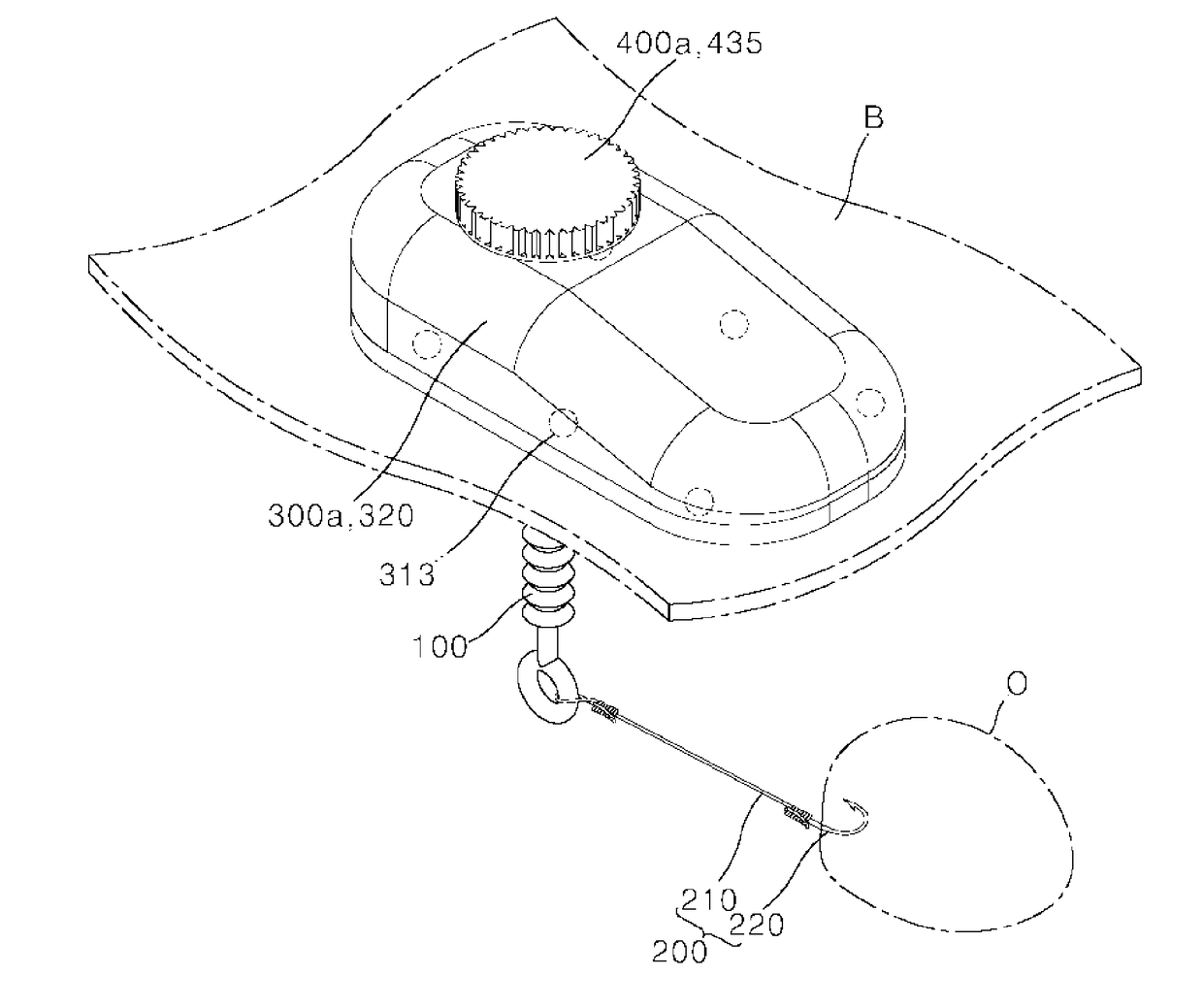
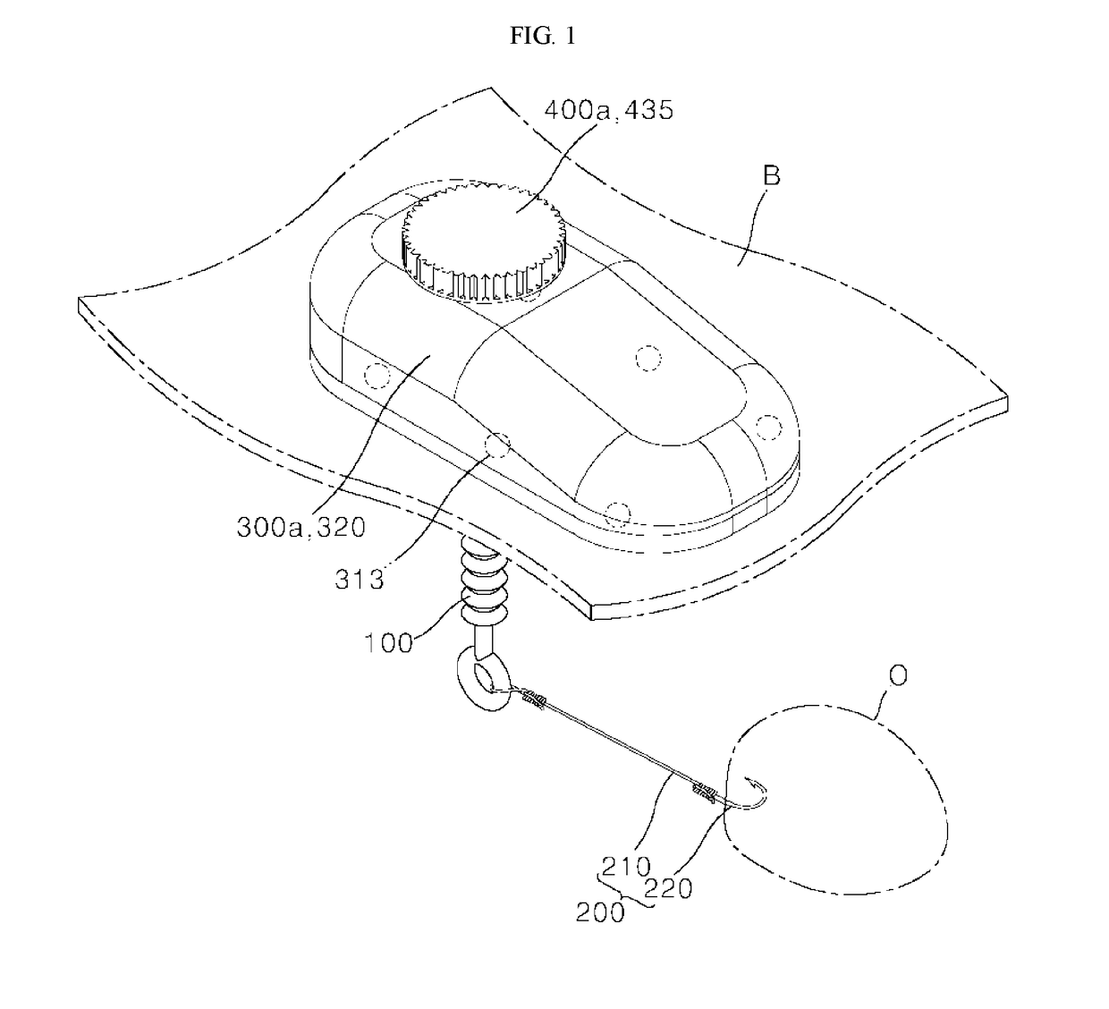
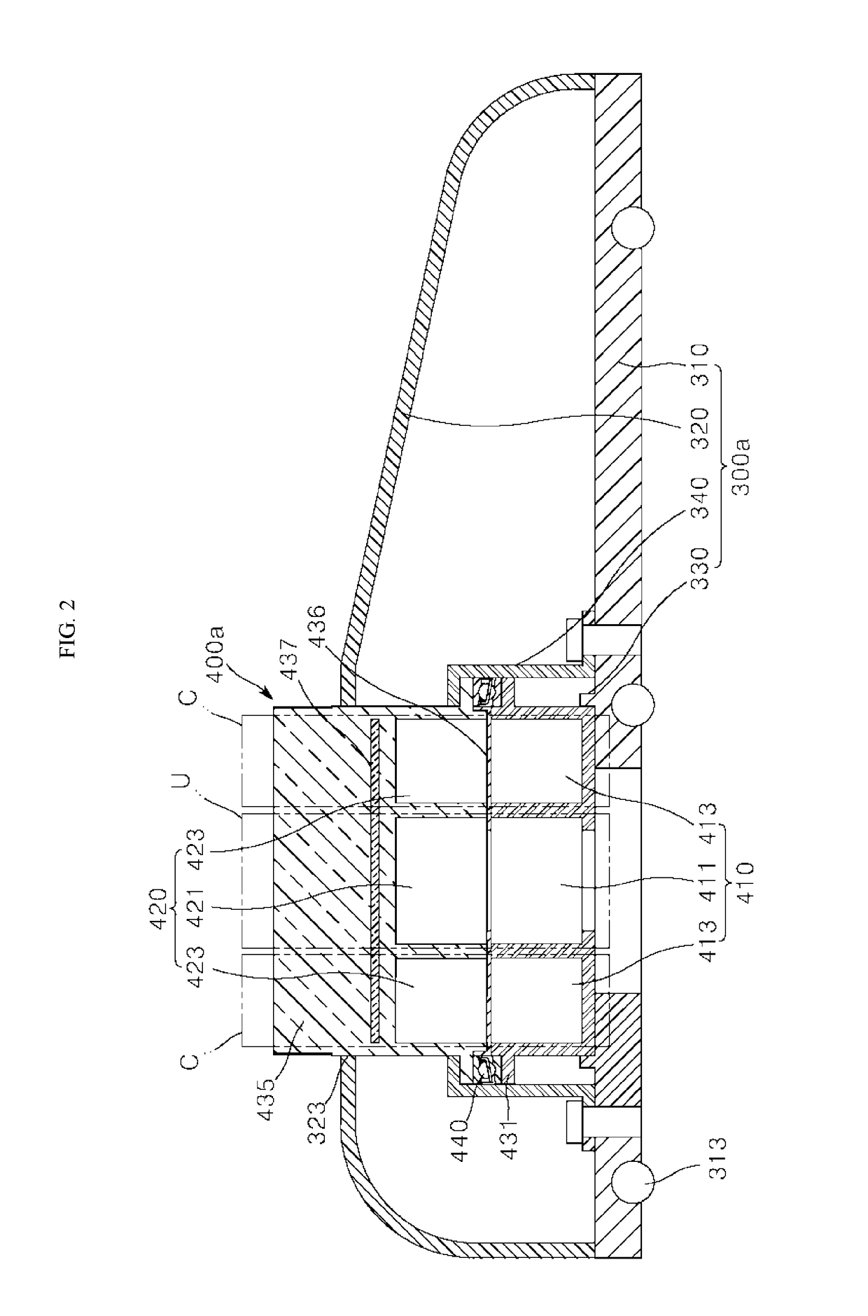
[0033]FIG. 1 is a perspective view schematically illustrating the surgical traction apparatus according to the first embodiment of the present invention, FIG. 2 is a cross-sectional view schematically illustrating an operating portion and a magnet portion according to the first embodiment of the present invention, and FIG. 3 is an exploded perspective view schematically illustrating the operating portion and the magnet portion according to the first embodiment of the present invention.

[0034]Referring to FIGS. 1 to 3, the surgical traction apparatus according to the first embodiment of the present invention includes a moving body portion 100, a hook portion 200, an operating portion 300a, and a magnet portion 400a.

[0035]The moving body portion 100 includes a magnetic body attached to a magnet and is inserted into a body. In the description of the present invention, “into a (the) body” ref...

second embodiment

[0083]Next, a surgical traction apparatus according to the present invention will be described.

[0084]Hereinafter, in the description of the surgical traction apparatus according to the second embodiment of the present invention, a detailed description that overlaps with the content of the surgical traction apparatus according to the first embodiment of the present invention which has been described with reference to FIGS. 1 to 4D will be omitted.

[0085]FIG. 5 is a perspective view schematically illustrating the surgical traction apparatus according to the second embodiment of the present invention, FIG. 6 is a cross-sectional view schematically illustrating an operating portion and a magnet portion according to the second embodiment of the present invention, and FIG. 7 is an exploded perspective view schematically illustrating the operating portion and the magnet portion according to the second embodiment of the present invention.

[0086]Referring to FIGS. 5 to 7, an operating portion ...


PUM


Abstract

A surgical traction apparatus according to the present invention includes a moving body portion including a magnetic body and configured to be inserted into a body, a hook portion configured to be connected to the moving body portion inside the body and pull an object inside the body, an operating portion configured to operate the moving body portion to move inside the body while moving outside the body, and a magnet portion configured to be mounted on the operating portion and be with adjustable magnetic strength.

Description

TECHNICAL FIELD[0001]The present invention relates to a surgical traction apparatus, and more particularly, to a surgical traction apparatus for remotely pulling organs or tissues inside a body from the body.BACKGROUND ART[0002]Generally, traditional laparotomy for treating a patient requires a large incision and causes much blood loss during surgery, which slows recovery of the patient after surgery and leaves a big scar, thus negatively affecting the patient's daily life.[0003]To overcome this disadvantage of laparotomy, novel surgical techniques such as minimally invasive surgery (MIS) using a laparoscope have recently been developed.[0004]One example of the related art is disclosed in Korean Utility Model Publication No. 20-2007-0000408 (published on Apr. 6, 2007 and entitled “The structure of Auvard Weighted Speculum adapted LED light with contamination prevention function”).DISCLOSURE OF INVENTIONTechnical Problem[0005]The present invention provides a surgical traction apparat...

Claims


Application Information

Patent Timeline
Patent Type & Authority Applications(United States)
IPC IPC(8): A61B17/02
CPCA61B2017/00876A61B17/0218A61B2017/00283A61B2017/00411A61B17/02A61B34/35
Inventor LEE, MOON GUJEON, YONG HOLEE, KIL YEONKIM, JAE SEUNG
Owner AJOU UNIV IND ACADEMIC COOP FOUND
Learn More