Head mounted display device with multiple segment display and optics

Inactive Publication Date: 2017-04-27
GOOGLE LLC
View PDF69 Cites 43 Cited by
  • Summary
  • Abstract
  • Description
  • Claims
  • Application Information

AI Technical Summary

Benefits of technology

The present disclosure relates to a head mounted display (HMD) device that utilizes a pair of laterally-curved display panels, one for each eye, and a corresponding set of optic element sub-assemblies to enable a small form factor and wider lateral field of view. The use of a single display panel with sections having different curvatures and angles permits the implementation of an HMD device with a form factor that more closely conforms to the user's eyes, reducing the bulky size and high moment of inertia associated with conventional HMD devices. The technical effects of the invention include a more immersive virtual reality and augmented reality experience, improved user experience, and reduced seam between the optical elements.

Problems solved by technology

However, the use of flat displays and a single lens for each eye often results in a bulky HMD form factor, which in turn imparts a high moment of inertia when in use.
The bulky size and limited field of view of these conventional HMD devices can deleteriously impact the user's sense of presence in the displayed image and thus inhibit the feeling of being immersed in the presented scene.
However, under this approach, the physical seams between the optics and between the display panels are often noticeable and thus detract from the experience.
Moreover, the characteristics of each display panel may differ, and thus render it difficult to achieve uniform color and brightness across the entire field of view.
Additionally, the design and fabrication of such systems is complex and thus can be cost-prohibitive.

Method used


Image

  • Head mounted display device with multiple segment display and optics
  • Head mounted display device with multiple segment display and optics
  • Head mounted display device with multiple segment display and optics

Examples


Embodiment Construction

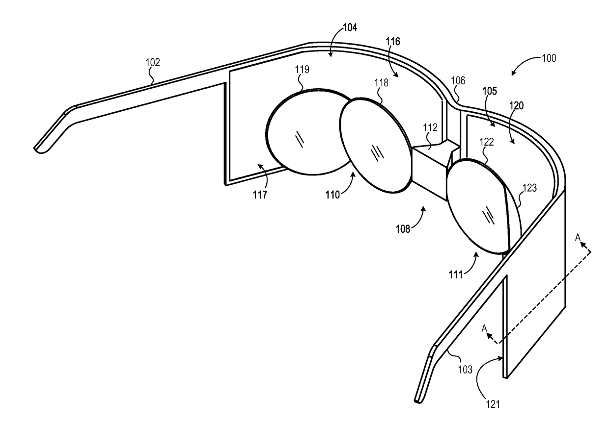
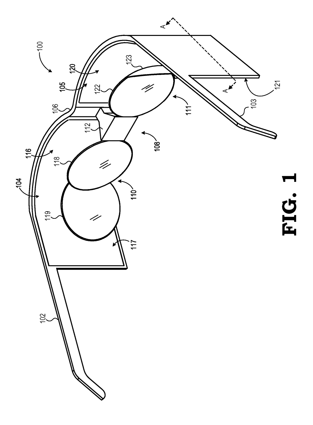
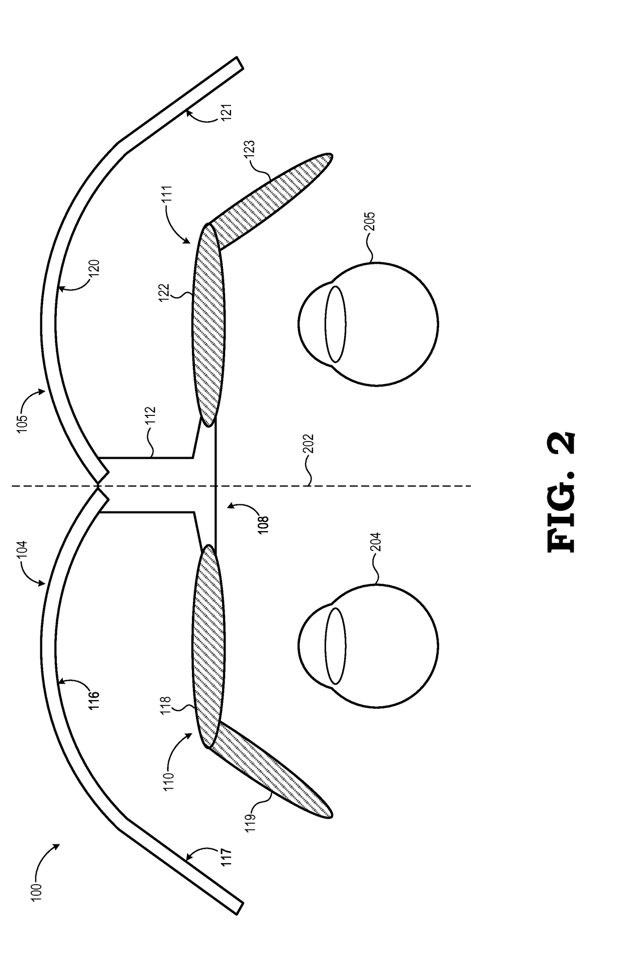
[0014]FIGS. 1-7 illustrate examples of an HMD device that utilizes two display panels, one for each eye, and a corresponding set of optic element sub-assemblies to enable a small form factor and wider lateral field of view. In at least one embodiment, the HMD device comprises a pair of laterally-curved display panels, one for each of the user's eyes, and an optical assembly comprising two optical sub-assemblies, one for each of the display panels. Each display panel may be independently driven by a separate display controller, and the display panels together may be operated to present a stereoscopic, or 3D, view of an AR or VR scene. Each display panel is logically divided in to two or more lateral sections, including a central field of view (FOV) section that is curved or substantially flat, and an adjacent peripheral field of view (FOV) section that may also may be curved or may be substantially flat. Each optical sub-assembly includes at least two lenses or other optical elements...


PUM


Abstract

A head mounted display (HMD) device includes first and second display panels laterally disposed about a medial plane. Each of the first and second curved display panels includes a first lateral section and an adjacent second lateral section. The first lateral section is adjacent to the medial plane and has a curvature with a first radius and the second lateral section is distal from the medial plane. The HMD further includes an optics assembly having first and second optics subassemblies disposed about the medial plane. Each of the first and second optics subassemblies includes a first optical element having an optical axis that intersects the first lateral section of a corresponding one of the first and second display panels and a second optical element having an optical axis that intersects the second lateral section of the corresponding one of the first and second display panels.

Description

BACKGROUND[0001]Field of the Disclosure[0002]The present disclosure relates generally to display devices and, more particularly, to head mounted display devices.[0003]Description of the Related Art[0004]Immersive virtual reality (VR) and augmented reality (AR) systems typically utilize a head mounted display (HMD) device that presents stereoscopic imagery to the user so as to give a sense of presence in a three-dimensional (3D) scene. Most conventional HMD devices implement either a single flat display that is separated into two independent display regions, one for the left eye and one for the right eye of the user, or a pair of independent flat displays, one for each eye of the user. Such devices also typically include a single lens for each eye so as to focus the entire image of the display into the user's eye. However, the use of flat displays and a single lens for each eye often results in a bulky HMD form factor, which in turn imparts a high moment of inertia when in use. Moreo...

Claims


Application Information

Patent Timeline
IPC IPC(8): G02B27/01H04N13/04G06T19/00G06T3/00
CPCG02B27/0172G06T3/0093H04N13/0429G06T19/006G02B2027/0178G02B2027/0123G02B2027/011G02B2027/014G02B2027/0134H04N13/332G02B25/001G06T3/18
Inventor HU, XINDACAROLLO, JERRY
Owner GOOGLE LLC
Why Eureka
Try Eureka