Wire harness

Inactive Publication Date: 2017-04-27
SUMITOMO WIRING SYST LTD
View PDF3 Cites 1 Cited by
  • Summary
  • Abstract
  • Description
  • Claims
  • Application Information

AI Technical Summary

Benefits of technology

The present invention provides a wire harness that prevents water from outside the wire harness from entering its interior, thereby improving its waterblocking performance. This is achieved through a foaming agent layer that forms a two-layer structure and fills gaps between the connector cover and the wires, preventing water from entering through these gaps. The wire harness is easy to wind and the foaming agent layer seals the gaps effectively, ensuring effective waterblocking. Overall, the invention improves the durability and reliability of the wire harness.

Problems solved by technology

However, when there are many electrical wires and the connector is large in size, an incline is formed on a connection portion of the insulated electrical wires and the connector, thus making it difficult to wind the covered member 7 without gaps.
However, depending upon the adhesive tape (such as the PVC tape), it is difficult to completely eliminate gaps between the connector cover and the PVC tape, and entry of water from outside the wire harness cannot be prevented completely.

Method used


Image

  • Wire harness
  • Wire harness
  • Wire harness

Examples


Embodiment Construction

[0025]The particulars shown herein are by way of example and for purposes of illustrative discussion of the embodiments of the present invention only and are presented in the cause of providing what is believed to be the most useful and readily understood description of the principles and conceptual aspects of the present invention. In this regard, no attempt is made to show structural details of the present invention in more detail than is necessary for the fundamental understanding of the present invention, the description taken with the drawings making apparent to those skilled in the art how the forms of the present invention may be embodied in practice.

[0026]In the following, an embodiment of the present invention is described with reference to the drawings.

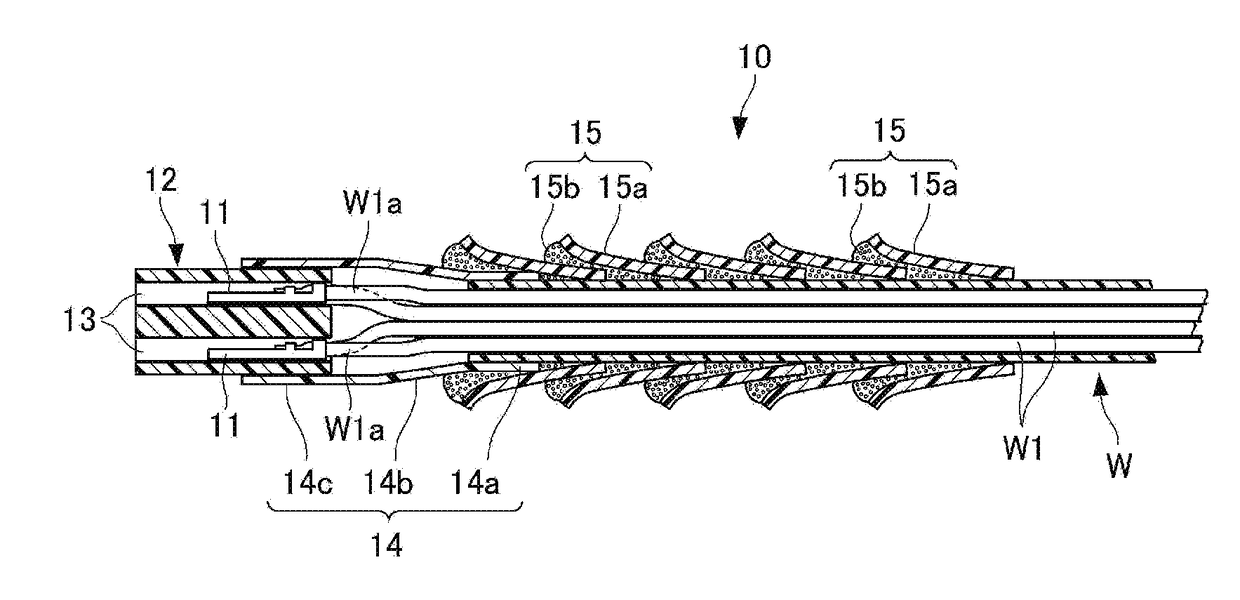
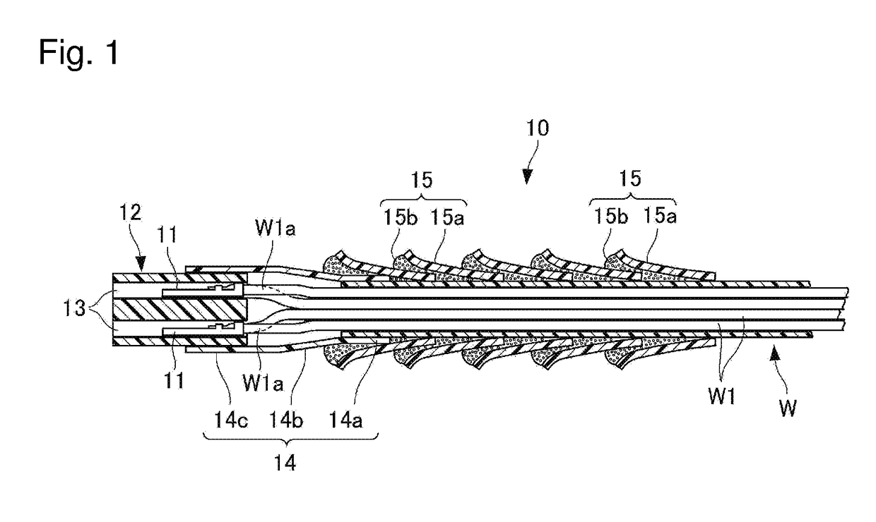
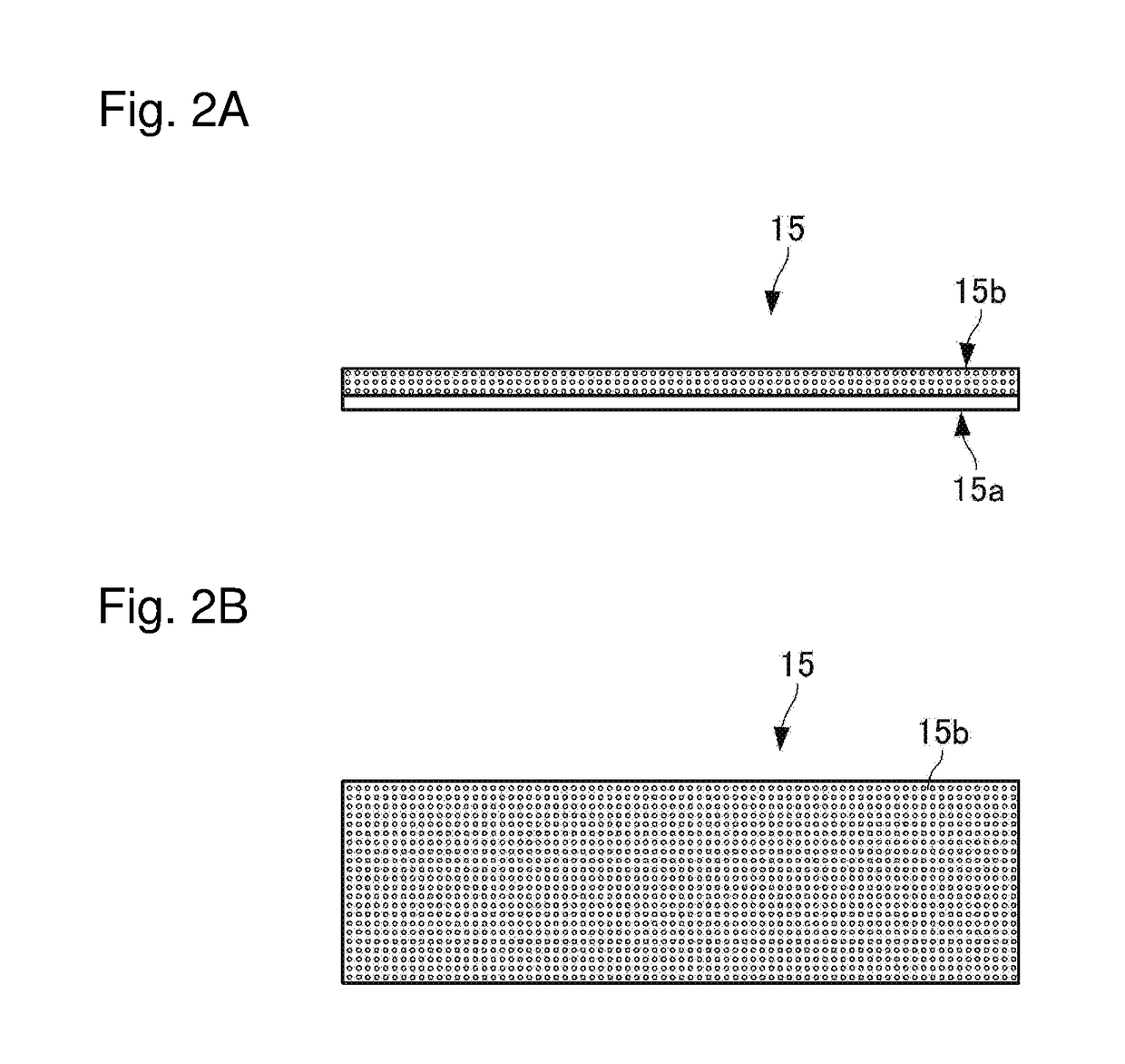
[0027]FIG. 1 is a longitudinal section view of a wire harness according to a first embodiment of the present invention. As illustrated in FIG. 1, a wire harness 10 includes a group of wires W, terminals 11, a connector 12, a...


PUM

PropertyMeasurementUnit
Thicknessaaaaaaaaaa
Thicknessaaaaaaaaaa

Abstract

A wire harness includes a group of wires having a plurality of covered electrical wires; a terminal provided to each lead wire end portion; a connector having a plurality of cavities which house and hold each terminal; a connector cover that is a resin mold body having a small opening tubular portion, a trumpet-shaped tubular portion, and a large opening tubular portion covering the connector; and a sheet fixating portion having a belt-like sheet wound over an area from the small opening tubular portion of the connector cover to a predetermined length of the covered electrical wires in a spiral form. The sheet fixating portion has a two-layer structure having a belt-like polyolefin sheet and a foaming agent layer, and is heated in a wound state with the foaming agent layer facing inward, the foaming agent layer foaming so as to fill gaps between the connector cover.

Description

CROSS-REFERENCE TO RELATED APPLICATIONS[0001]The present application claims priority under 35 U.S.C. §119 of Japanese Application No. JP2015-209988, filed on Oct. 26, 2015, the disclosure of which is expressly incorporated by reference herein in its entirety.BACKGROUND OF THE INVENTION[0002]1. Field of the Invention[0003]The present invention relates to a waterproofed wire harness used to connect electrical wires in automobiles and the like.[0004]2. Description of Related Art[0005]In wire harnesses that are installed in automobiles and the like, a protective structure has been proposed such as a waterproofing structure to prevent water from entering from outside into a gap between an electrical wire and a connector connected to an end portion thereof. In Japanese Patent Laid-Open Publication No. 2013-187004, for example, a configuration is disclosed in which the gap between the electrical wire and the connector is covered by an adhesive tape.[0006]A connector-provided electrical wir...

Claims


Application Information

Patent Timeline
IPC IPC(8): H01B7/282H01B7/02H01B3/44H01R13/52H01B7/00
CPCH01B7/2825H01R13/5221H01B7/0216H01B3/441H01B7/0045B60R16/0215H01R13/5202H01R13/5205H01R13/5216H01R2201/26
Inventor WAKABAYASHI, MASATAKAARAGIRI, SHOTA
Owner SUMITOMO WIRING SYST LTD
Why Eureka
Try Eureka