Method of converting high voltage ac lines into bipolar high voltage DC systems

a high-voltage dc system and high-voltage ac technology, applied in the field of power transmission lines, can solve problems such as affecting system reliability and adding more complexity

Inactive Publication Date: 2017-04-27
QATAR UNIVERSITY +1
View PDF9 Cites 10 Cited by
  • Summary
  • Abstract
  • Description
  • Claims
  • Application Information

AI Technical Summary

Benefits of technology

[0008]The method of converting high voltage AC lines into bipolar high voltage DC systems includes the use of three wires in a three-wire mode, wherein the positive pole is always considered as a go-wire, while the negative pole is always considered as a return wire. In one state, the third pole (modulating pole) is activated to be a go-wire with the positive pole via closing a switch for a certain time duration. As a result, the supply current will be divided equally between the positive pole and the modulating pole (due to similar lines resistances, assuming negligible mismatch between lines' impedances), while the entire current returns in the negative pole. In a second state, the third pole (modulating pole) is activated to be a return wire with the negative pole via closing a second switch for a certain time duration. As a result, the supply current will flow only through the positive pole, and the return path is split between the modulating pole and the negative pole. Switching is required due to thermal considerations. To avoid abrupt changes in current during transitions, additional resistors are successively inserted in series with the modulating pole and removed during transitions. The three wires may be used in two-wire mode (only the positive and negative poles) during low power levels.
[0009]These and other features of the present invention will become readily apparent upon further review of the following specification and drawings.

Problems solved by technology

This affects system reliability and adds more complexity.

Method used


Image

  • Method of converting high voltage ac lines into bipolar high voltage DC systems
  • Method of converting high voltage ac lines into bipolar high voltage DC systems
  • Method of converting high voltage ac lines into bipolar high voltage DC systems

Examples


Embodiment Construction

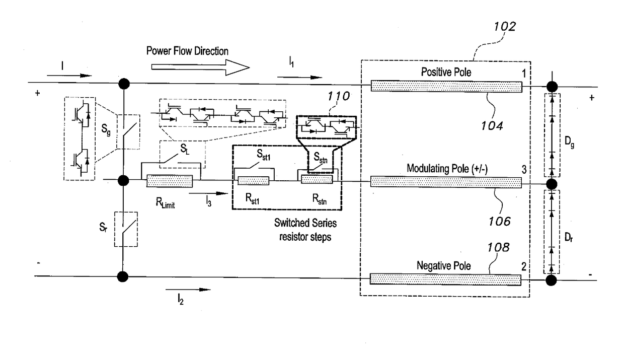
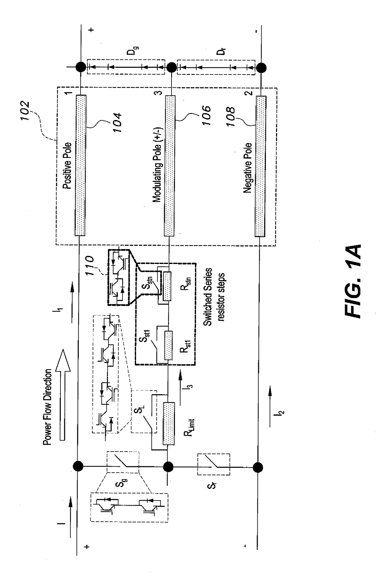
[0041]As shown in FIG. 1A, the method of converting high voltage AC lines into bipolar high voltage DC systems makes use of the three transmission lines 102 in an existing high voltage AC system as transmission lines in a bipolar high voltage DC system, e.g., for the transmission of power from a DC source (such as a wind power electric generator) to a power grid. According to the method, the three transmission lines 102 are used in a three-wire mode when the source current exceeds the rated thermal current limit of the transmission lines 102, and are used in a two-wire mode when the source current is at or below the rated thermal current limit of the transmission lines 102. For purposes of explanation, one of the transmission lines 102 is referred to as the positive pole 104, a second transmission line is referred to as the modulating pole 106, and a third transmission line is referred to as the negative pole 108.

[0042]The method involves inserting switches Sg and Sr in series betwe...


PUM


Abstract

The method of converting high voltage AC lines into bipolar high voltage DC systems makes use of the three transmission lines (referred to as the positive pole, the negative pole, and the modulating pole) in an existing high voltage AC system as transmission lines in a bipolar high voltage DC system. When current from the power source is up to the thermal current limit of the transmission lines, the transmission lines operate in two-wire mode, where current is delivered in the positive pole and returned in the negative pole, the modulating pole being open. When power source current exceeds the thermal current limit, operation is in three-wire mode, alternating for predetermined periods between parallel configuration of the positive pole and the modulating pole to divide current for delivery to the load, and parallel configuration of the negative pole and the modulating pole, dividing the return current.

Description

CROSS-REFERENCE TO RELATED APPLICATION[0001]This application claims the benefit of U.S. Provisional Patent Application Ser. No. 62 / 245,205, filed Oct. 22, 2015.BACKGROUND OF THE INVENTION[0002]1. Field of the Invention[0003]The present invention relates to power transmission lines, and particularly to a method of converting high voltage AC lines into bipolar high voltage DC systems.[0004]2. Description of the Related Art[0005]There is growing interest in the development of renewable energy sources, such as wind power. Many wind power stations are located offshore and transmit power onshore through submerged high voltage DC lines. However, for historical reasons, existing onshore power transmission lines are based on three-phase high voltage AC transmission line systems. In order to take maximum advantage of the existing power transmission infrastructure while reducing costs, it would be desirable to convert existing AC power transmission lines for use as high voltage DC transmission...

Claims


Application Information

Patent Timeline
Patent Type & Authority Applications(United States)
IPC IPC(8): H02M7/06H02M1/32
CPCH02M1/32H02M7/06H02J3/02H02J4/00H02J1/08H02M7/7575Y02E60/60
Inventor AHMED, SHEHABELSEROUGI, AHMED A.MASSOUD, AHMED M.ABDEL-KHALIK, AYMAN S.
Owner QATAR UNIVERSITY
Why Eureka
Try Eureka