Subsea cooling assembly

a cooling assembly and subsea technology, applied in the direction of cooling/ventilation/heating modifications, electrical apparatus casings/cabinets/drawers, printed circuit board receptacles, etc., can solve the problems of increasing the number of failure modes, not very efficient, and adding complexity

Inactive Publication Date: 2017-04-27
FMC KONGSBERG SUS
View PDF4 Cites 1 Cited by
  • Summary
  • Abstract
  • Description
  • Claims
  • Application Information

AI Technical Summary

Benefits of technology

[0020]The electronics or power components may be positioned on a mounting surface of the at least one recess. The electronics or power components may be mounted directly or indirectly to the mounting surface in a manner that allows for satisfactory transfer of heat from the electronics or power components to the block module. The mounting surface may be any of the surfaces of the recess, and in one aspect the bottom surface of the recess may serve as a mounting surface, thereby facilitating the installation of the power and electronic components into the recess.
[0021]The exterior of the block module may be provided with at least one cooling rib to enhance the cooling effect of the cooling assembly. In one aspect the longitudinal direction of the cooling rib may be perpendicular to the direction of the strength supporting structure across the block element. The combination of the strength supporting structure and the cooling ribs arranged perpendicular to the strength supporting structure provides the cooling assembly with an overall stiffness suitable for withstanding pressure loads when submerged at considerable sea depths. The overall stiffness of the cooling arrangement may also be improved by increasing the thickness of the block module and the cover element.
[0022]In addition or as an alternative to the cooling ribs, the block module may be provided with a cooling arrangement comprising at least one cooling pipe element to increase the cooling effect of the cooling assembly.

Problems solved by technology

A problem with this system that still has to been solved is how to ensure the efficient transfer of heat between the electronic or power components and the seawater.
This solution has several disadvantages: the heat from the power components needs to be transferred through a number of heat conducting elements that are arranged in series and out to the seawater and this is not very efficient.
This solution provides effective cooling but adds complexity and increases the number of failure modes compared to a passive system.
However, the plate at the top will buckle at higher pressures as it is not supported otherwise than along the outer rim.

Method used


Image

  • Subsea cooling assembly
  • Subsea cooling assembly

Examples


Embodiment Construction

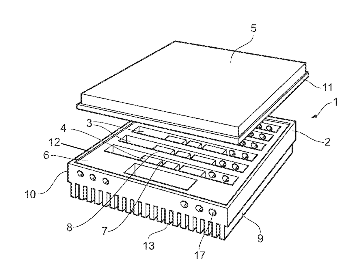
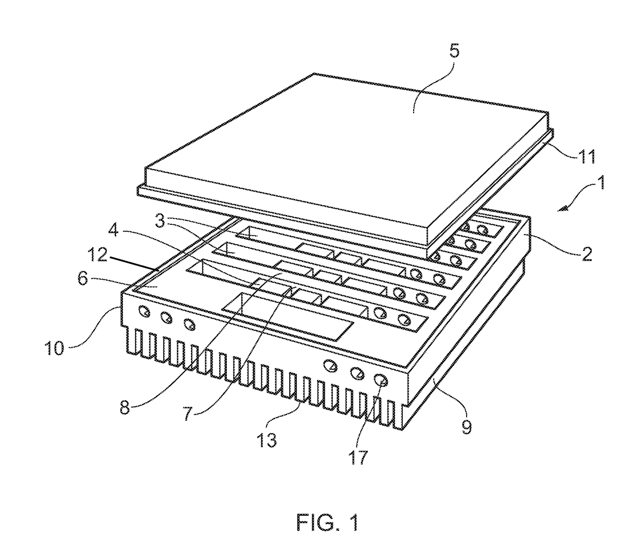
[0031]FIG. 1 shows an example of a subsea cooling assembly 1 in accordance with the invention, wherein a block module 2 has a recessed surface 6 arranged with a number of recesses 3 for accommodating electronics or power components 4. The electronics or power components 4 are placed in the recesses 3 in direct or indirect contact with a component mounting surface of the recess, for instance the bottom surface of the recess. In FIG. 1, the recesses 3 are shown having essentially equal size and are spaced side by side in a parallel relationship with essentially an equal distance between the recesses. However, the configuration and dimensions of the recesses may vary according to the kind of electronics or power components 4 to be accommodated in the recesses.

[0032]Each recess 3 may have an oblong shape as illustrated in FIG. 1 with a length extending from one side portion 9 to an oppositely arranged side portion 10, and each recess may be arranged with a varying or uniform depth. The ...


PUM


Abstract

A subsea cooling assembly has a block module for the accommodation of electronics or power components and a cover element. The block module is arranged with at least one recess, with the electronics or power components being arranged in the at least one recess of the block module for the transfer heat between the electronics or power components and the surrounding sea through the block module. The cover element has outer rim portions arranged to fit with outer rim portions of the at least one recess for closing off the interior of the at least one recess. The block module has at least one strength supporting structure arranged to provide load support to at least a portion of the cover element which is distanced away from the outer rim portions of the cover element.

Description

[0001]The invention concerns a subsea cooling assembly, and a subsea system including at least two subsea cooling assemblies.[0002]In accordance with the invention, the subsea cooling assembly is applied for the cooling of electronics or power components. The electronics or power components may be used for controlling or manipulating the characteristics of a motor. For instance, the electronics or power components may comprise a variable speed drive employed to control the speed of a motor of a compressor, a water pump, a fan or other devices wherein a variable speed motor may be used for varying the speed of the motor.[0003]Typical electronics or power components for enclosure in the subsea cooling assembly in accordance with the invention may include IGBTs, MOSFETs, diodes, thyristors, GTOs, inductors, transformers, resistors, capacitors, gate drivers, power supplies, batteries, control electronics, etc.FIELD OF THE INVENTION[0004]One field of use for the subsea cooling assembly i...

Claims


Application Information

Patent Timeline
Patent Type & Authority Applications(United States)
IPC IPC(8): H05K7/20
CPCH05K7/20236H05K7/209H05K7/20409H05K7/20336H05K7/20927H05K7/14337H05K5/069H05K7/20436H05K7/1432
Inventor FOLKNER, STEIN
Owner FMC KONGSBERG SUS
Why Eureka
Try Eureka