Atomization assembly and electronic cigarette

a technology of electronic cigarettes and atomization parts, which is applied in the direction of ohmic-resistance heating, tobacco, electrical equipment, etc., can solve the problems of needing to improve, bad experience for users, and some defects in prior art, and achieves convenient assembly, stable amount of smoke, and good taste.

Inactive Publication Date: 2017-05-04
KIMREE HI TECH
View PDF3 Cites 53 Cited by
  • Summary
  • Abstract
  • Description
  • Claims
  • Application Information

AI Technical Summary

Benefits of technology

[0040]By implementing the atomization assembly and the electronic cigarette of the present invention, the following advantages may be obtained. By means of the arrangement that the oil storage element and the atomization core cooperate with each other, and one end of the atomization core is inserted into the oil storage element while a smoke outlet is defined at the other end of the atomization core, the smoke passageway for discharging the smoke never runs through the oil storage region. Therefore, it is hard for the tobacco oil to be leaked to the smoke passageway and it is hence hard for users to suck the condensed tobacco oil. Meanwhile, by means of the arrangement that a blocking part is defined on the electrode assembly of the atomization assembly, an air-vent hole connected both to an exterior of the electronic cigarette and an interior of the atomization cavity is defined at one side of the blocking part, opposite to the battery assembly, and the atomization tube is configu...

Problems solved by technology

Therefore, it brings bad experience to users.
Therefore,...

Method used


Image

  • Atomization assembly and electronic cigarette
  • Atomization assembly and electronic cigarette
  • Atomization assembly and electronic cigarette

Examples


first embodiment

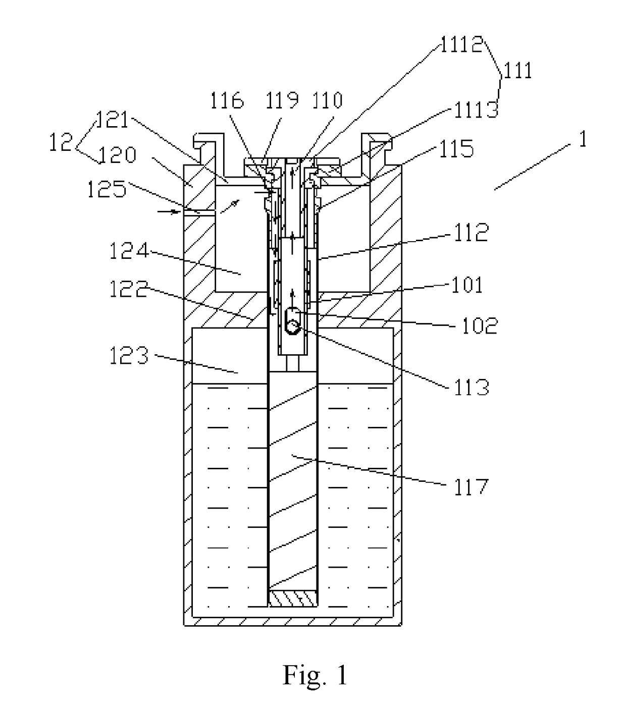
[0067]In addition, there is no limit to the shape of the air-vent hole 116 in the present application. The air-vent hole 116 can either be a circular hole or a waist-shaped hole. The shape of the air-vent hole 116 shown in the first embodiment is circular.

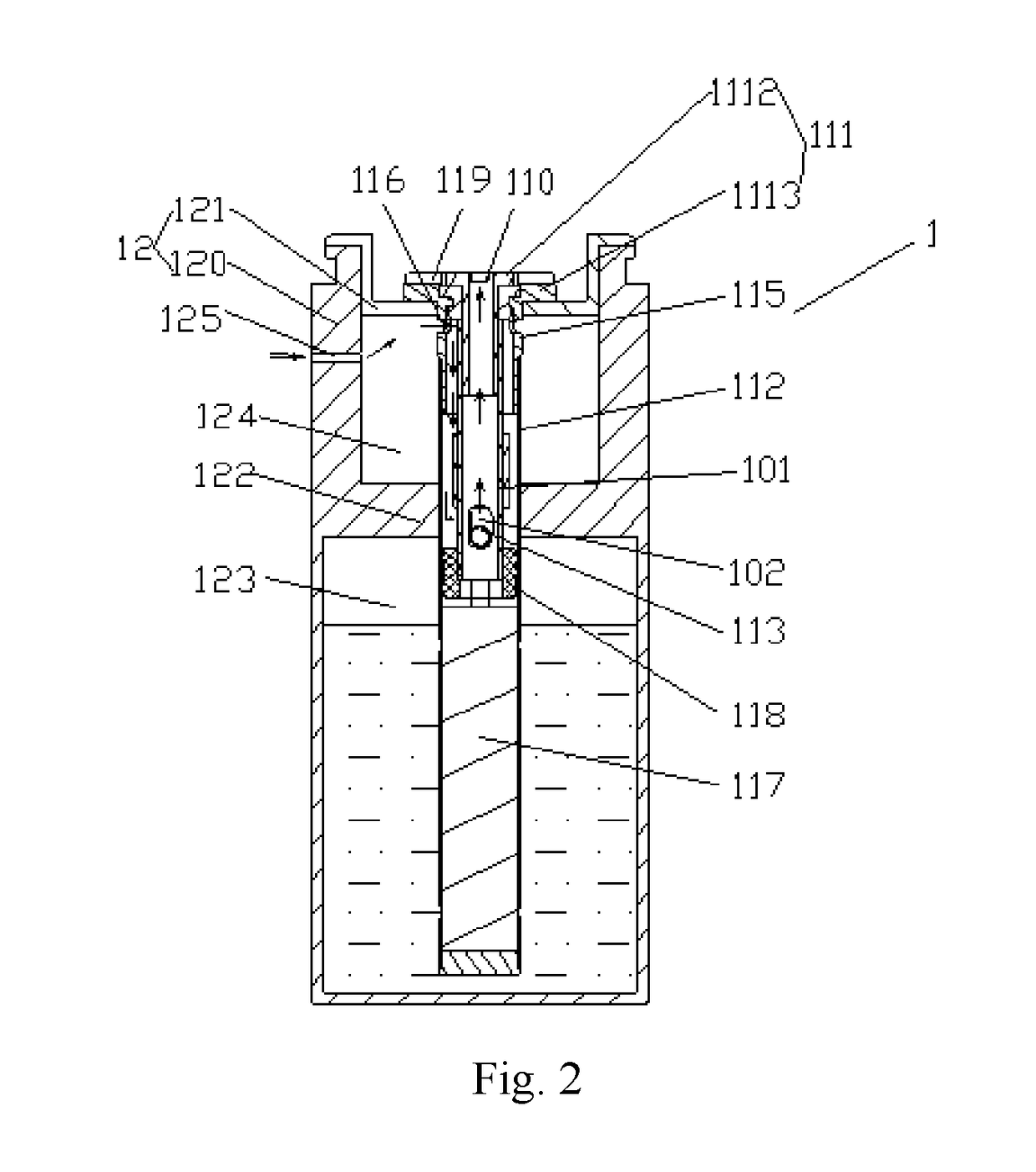
[0068]FIG. 2 shows an atomization assembly 1 according to a second embodiment of the present application. The air inlet 125 is a waist-shaped hole, which is different from the first embodiment. When the air inlet 125 is a waist-shaped hole, the inflow speed can be reduced to prevent from generating noise.

second embodiment

[0069]In addition, an atomization base 118 configured for placing the heating wire assembly 113 is further defined in the atomization cavity in the Due to the existing of the atomization base 118, the following circumstance can be all avoided: that the tobacco oil in the oil guiding part 117 permeates into the atomization cavity heavily, thus the tobacco oil can't be atomized thoroughly and the tobacco oil hence can be sucked easily.

[0070]Especially, in order to obtain a better sealing effect, a sealing element (not shown) is configured between an outer wall of the atomization base 118 and an inner wall of the atomization tube 112. The sealing element is a gasket configured to sheathe the atomization base 118.

[0071]Preferably, the atomization base 118 is made of ceramic By using ceramic material, the thermo-tolerance of the atomization base 118 is better. The lifetime of the atomization assembly 1 is hence longer.

[0072]In the second embodiment, the rest configurations of the atomiz...


PUM


Abstract

The present application provides an atomization assembly and an electronic cigarette, the atomization assembly comprises an atomization core and an oil storage element. The atomization core comprises an electrode assembly, an atomization tube configured to sheathe the electrode assembly and insert into the oil storage element. A blocking part is defined on an outer surface of the electrode assembly. An air-vent hole is defined at one end of the blocking part of the electrode assembly close to the battery assembly; the atomization tube is positioned at the other end of the blocking part. In the atomization assembly or the electronic cigarette of the present application, it is hard for the tobacco oil to be leaked to airflow passageway, hard for user to suck condensed tobacco oil and easy for assembling.

Description

TECHNICAL FIELD[0001]This invention relates to the field of products of electric heaters, and more particularly to an atomization assembly and an electronic cigarette.BACKGROUND OF THE INVENTION[0002]The prior electronic cigarette usually includes an atomization assembly and a battery assembly connected to each other. One end of the atomization assembly, opposite to the battery assembly, is used as a mouthpiece for a user to smoke. The atomization assembly comprises a heating wire assembly for atomizing tobacco oil, an oil storage cotton for storing the tobacco oil, and a wick for guiding the tobacco oil to the heating wire assembly. A smoke passageway formed to run through the oil storage cotton is formed in the atomization assembly. Users suck the smoking formed by the heating wire assembly atomizing the tobacco oil via the smoke passageway.[0003]As the position of the oil storage cotton is close to the mouthpiece and the smoke passageway is in an oil storage region, it is easy fo...

Claims


Application Information

Patent Timeline
IPC IPC(8): A24F47/00H05B1/02A24F40/10A24F40/485A24F40/50
CPCA24F47/008H05B1/0244H05B2203/021A24F40/10A24F40/50A24F40/485
Inventor LIU, QIUMING
Owner KIMREE HI TECH
Why Eureka
Try Eureka