
Helmet and helmet system

a helmet and helmet technology, applied in the field of helmets and safety devices, can solve the problems of 70% of bicycle accidents, head impacts or other bodily harm, and most bicycle helmets are not designed to prevent, so as to enhance the safety of the rider

Inactive Publication Date: 2017-05-04
LUMEN LABS HK LTD
View PDF17 Cites 25 Cited by
  • Summary
  • Abstract
  • Description
  • Claims
  • Application Information

AI Technical Summary

Benefits of technology

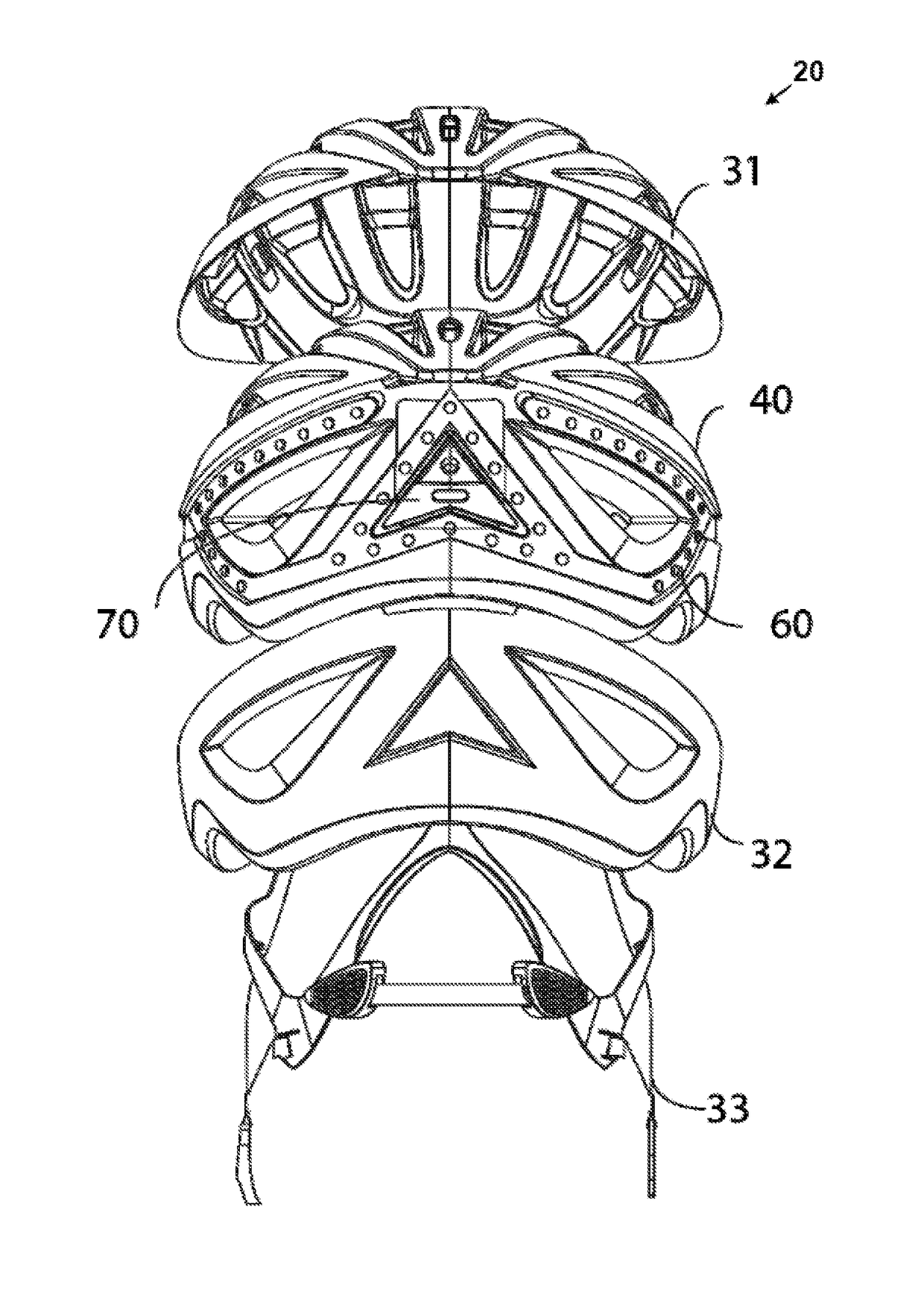
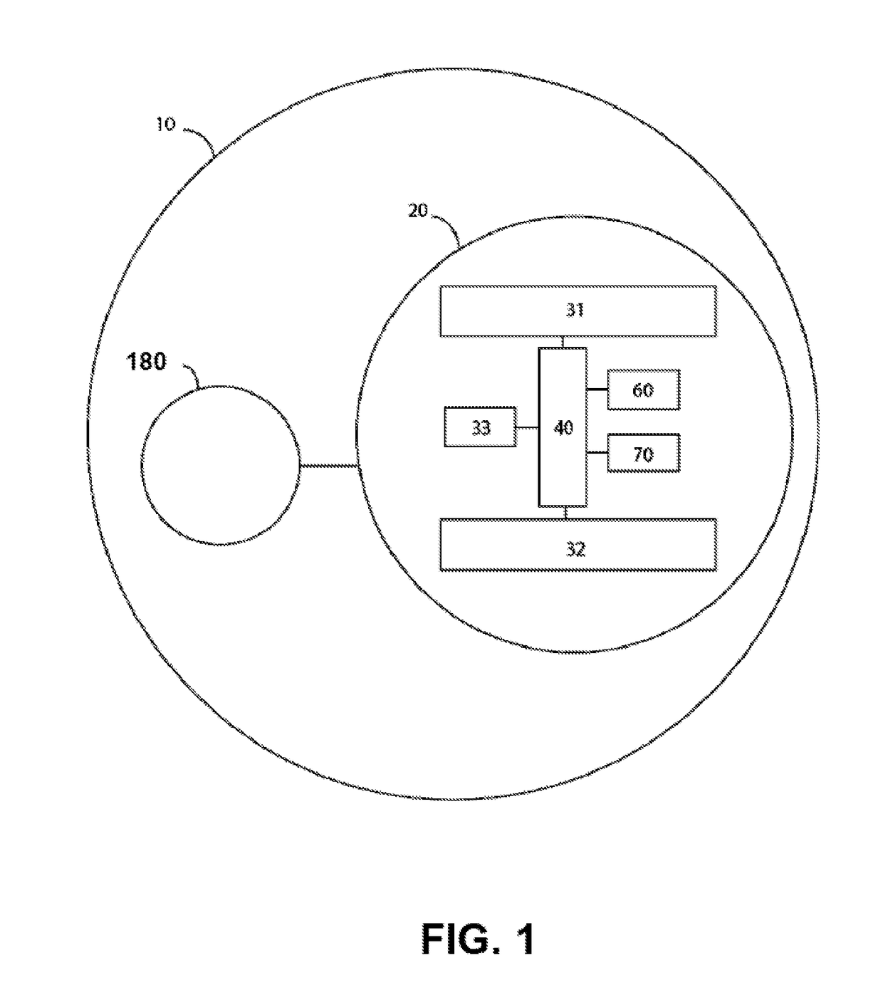
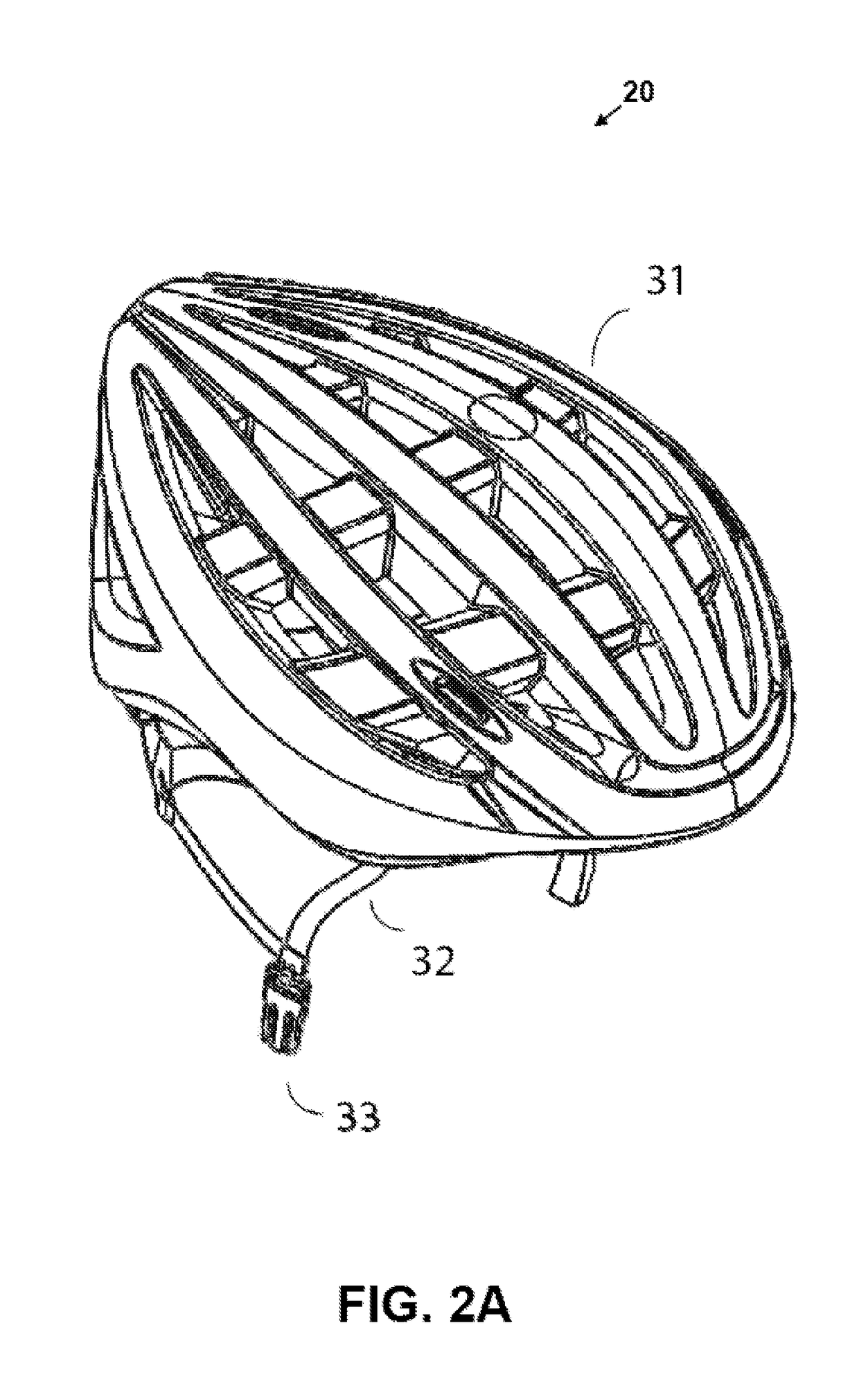
The present invention is for a helmet for riders that aims to provide more safety and protection. This helmet has a LED strip attached to it, which helps to make the rider more visible to cars and pedestrians and also protects the head with a liner. The LED strip has multiple LEDs, including front and back lights, as well as additional lights for the brim. The helmet also has an electronics box that has a cover, bottom, wing, and cavity to absorb impact energy and prevent compression of the helmet foam during an impact. Overall, the helmet provides more visibility and safety for riders on vehicles.

Problems solved by technology

However, most bicycle helmets are not designed to prevent accidents that may result in head impacts or other bodily harm.
Taken together, 70% of bicycle accidents are due to a combination of poor cyclist visibility and improper adherence to road rules.
The conventional bicycle helmet is limited to reactively minimizing impact to the head.
This conventional design minimizes head trauma in the event of an impact, but it does not help cyclists avoid impact by being more visible on the road, especially in darkening or dark environments when most accidents occur.
These solutions are insufficient as most lights and reflectors are too small to be seen or are not bright enough to be seen from a safe following distance.
The lack of a standardized, common lighting system can result in motorists, other cyclists and pedestrians not adequately seeing cyclists.
Furthermore, helmets have thus far not been well utilized as a platform for additional technology enhancements.
However, thus far, few have been brought to the market.
However, doing so effectively means removing protective material from the helmet, decreasing its ability to pass the impact tests required of the EN1078 and the CPSC 16 C.F.R part 1203.

Method used


Image

  • Helmet and helmet system
  • Helmet and helmet system
  • Helmet and helmet system

Examples


Embodiment Construction

[0032]The present invention provides a smart helmet and a mechanical design thereof, enabling one to create a helmet that (1) incorporates electronics onto the helmet in such a way that the electronics are effectively hidden from a user, and (3) still passes prevailing safety standards for helmets.

[0033]Although the invention is hereinafter described in embodiments predominantly based on an example application of the invention to a rider on a bicycle, the present invention is not limited only to applications to bicycles. The present invention is applicable to any vehicles, such as motorcycles, where riders on these vehicles wear helmets for safety and protection.

[0034]Exemplarily, the present invention is described by illustrating an exemplary embodiment of the smart helmet and its mechanical design as follows.

OVERVIEW OF THE PRESENT INVENTION

[0035]In accordance with the exemplary embodiment, a protective smart helmet is integrated with one or more brake lights, one or more turn sig...


PUM


Abstract

A protective helmet system (10) that integrates turn signal light, break signal light, motion sensors (710), Bluetooth connectivity and a remote control (180) is provided. The system (10) comprises a helmet (20) for providing protection and enhancing safety to a rider on a vehicle, and a remote control (180) for wirelessly controlling electronics in the helmet (20) to perform functions. The helmet (20) comprises a LED strip (60). The LED strip (60) comprises a flexible base (68) and a plurality of LEDs (62, 63, 64, 65, 66, 671, 672, 673) installed on the flexible base (68). In addition, the LED strip (60) is configured to produce light signals to cars and pedestrians surrounding the rider, causing the rider to be more visible to the surrounding cars and pedestrians to thereby promote safety to the rider.

Description

CROSS-REFERENCE TO RELATED APPLICATIONS[0001]This application claims priority to U.S. Provisional Patent Application No. 62 / 126,579, filed on Feb. 28, 2015, the disclosure of which is incorporated by reference herein in its entirety.FIELD OF THE INVENTION[0002]The present invention relates to helmets and safety devices for protecting riders of vehicles, including bicycles and motorcycles.BACKGROUND[0003]The helmet is intended to protect the head in the event of impact. However, most bicycle helmets are not designed to prevent accidents that may result in head impacts or other bodily harm. According to the Boston Cyclist Safety Report 2013 published in May 2013 and by the City of Boston, the disclosure of which is incorporated by reference herein, 32% of bicycle accidents are due to motorists not seeing the cyclists; this includes 18% of bicycle accidents that result from “dooring”, i.e. when a vehicle door is extended into cyclists (p. 17 of Boston Cyclist Safety Report 2013). Anoth...

Claims


Application Information

Patent Timeline
Patent Type & Authority Applications(United States)
IPC IPC(8): A42B3/04A42B3/08A42B3/30B60Q1/38F21V23/02F21V23/04B60Q1/26B60Q1/44A42B3/12F21V33/00
CPCA42B3/0453F21Y2113/13A42B3/125A42B3/08A42B3/30F21V33/008F21V23/023F21V23/0471F21V23/0407F21V23/0435B60Q1/2676B60Q1/44B60Q1/38F21W2111/10F21Y2115/10F21Y2103/10A42B3/044A42B3/0433
Inventor CHEN, HAORANDING, EU-WEN
Owner LUMEN LABS HK LTD
Learn More