Surgical instrument

Inactive Publication Date: 2017-05-04
HEINEMANN NORBERT
View PDF6 Cites 8 Cited by
  • Summary
  • Abstract
  • Description
  • Claims
  • Application Information

AI Technical Summary

Benefits of technology

[0004]The object of the invention is therefore to make available an improved surgical instrument, in particular an arthroscopy punch,

Problems solved by technology

Therefore, the forces acting on the surgical instrument, and in particular on the bearing of the movable jaw part, are considerable.
Although this ensures a stable bearing of the pull rod in the movable jaw part, the instrument cannot be dismantled for cleaning purposes.
To be able to dismantle the instrument, a toolmaker with a suitable tool is needed, which means that dismantling is not feasible in practice.
In addition, given the absence of guiding in translation on the tube part, the pull rod has to be configured with a relatively large diameter, which is disad

Method used


Image

  • Surgical instrument
  • Surgical instrument
  • Surgical instrument

Examples


Embodiment Construction

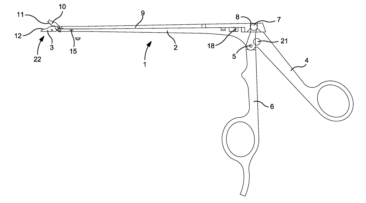
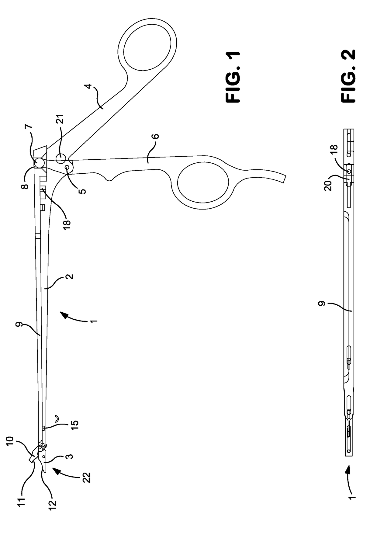
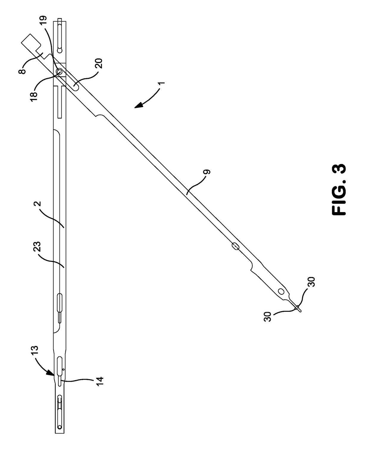
[0039]In FIGS. 1 to 3, a preferred illustrative embodiment of a surgical instrument 1 according to the invention, designed as an arthroscopy punch, is shown in its entirety. The surgical instrument 1 comprises an elongate, stationary shaft 2 with a distal (front) working end, which is partially formed by a stationary jaw part 3 formed in one piece with the shaft 2. A rear grip part 4 (grip branch) is also formed in one piece with the shaft 2.

[0040]A distal (front) pivotable grip part 6 is arranged to be pivotable, relative to the stationary rear (proximal) grip part 4, about a pivot axis 5 extending transversely with respect to the longitudinal extent of the shaft 2.

[0041]The pivotable (front) grip part 6 has an upper end 7 which has the approximate shape of a spherical head and which engages in a laterally open cutout 8 of a sliding part 9 arranged on the shaft 2. In this way, the sliding part 9 can be driven longitudinally displaceably along the longitudinal extent of the shaft 2 ...


PUM


Abstract

A surgical instrument, in particular an arthroscopy punch, with a jaw (22), includes a stationary jaw part (3) and a movable jaw part (10) which, by pivoting of a pivotable grip part (6), is displaceable relative to the stationary jaw part (3), between a closed position and an open position, in a slotted guide (26) along a curved guide path.

Description

BACKGROUND OF THE INVENTION[0001]The invention relates to a surgical instrument, in particular an arthroscopy punch, with a jaw, comprising a stationary jaw part and a movable jaw part which, by pivoting of a pivotable grip part, is displaceable relative to the stationary jaw part, between a closed position and an open position, in a slotted guide along a curved guide path.[0002]Arthroscopy punches are used to remove cartilaginous joint parts, or very hard muscles or muscle strands such as the meniscus muscle. Therefore, the forces acting on the surgical instrument, and in particular on the bearing of the movable jaw part, are considerable. In order to counter this problem, U.S. Pat. No. 4,712,545 proposed a surgical instrument in which the movable jaw part is displaceable relative to the stationary jaw part in a slotted guide along a curved guide path, such that the acting forces are not just supported at individual points on a hinge axis but instead across a large surface area on ...

Claims


Application Information

Patent Timeline
IPC IPC(8): A61B17/16A61B17/32
CPCA61B17/1608A61B2017/00438A61B17/320016A61B2017/2902A61B2017/2934A61B2017/294A61B2090/0813
Inventor HEINEMANN, NORBERT
Owner HEINEMANN NORBERT
Why Eureka
Try Eureka