Measuring apparatus and method for three-dimensional measurement of an oral cavity

a three-dimensional measurement and measuring apparatus technology, applied in the field of three-dimensional measurement of an oral cavity, can solve the problems of manual alignment, impeded complete measurement of the poorly visible surfaces manual alignment of the rows of teeth, so as to achieve fast and complete measurement of the palate

Active Publication Date: 2017-05-04
QUARZ PARTNERS
View PDF16 Cites 17 Cited by
  • Summary
  • Abstract
  • Description
  • Claims
  • Application Information

AI Technical Summary

Benefits of technology

[0078]In a particularly preferred embodiment, in which the lateral measuring members are arranged pivoting on a central measuring member, the lateral measuring members can at least be pivoted between a first position, in which the internal angles facing the measuring space are at most 90° and a second position in the range of 135°-170°. This position of the lateral measuring members allows to abut the measuring head in the oral vestibule (vestibulum) on the oral mucosa of the alveolar ridges of the closed upper and lower jaw rows of teeth and to measure the closed bite as well as the lateral movements of the lower jaw with respect to the upper jaw. In this position the guiding members at the free end of the lateral-measuring members can serve as supports for the central measuring member, which by the angular position of the lateral measuring members with its me

Problems solved by technology

Application problems exist with scanners of this type when acquiring data from poorly visible surface parts, e.g. for interdental to mesial or distal-oriented natural tooth surfaces as well as for fine-detailed, partly vertical geometrical preparation surfaces.
Thereby, a complete measurement of the poorly visible surfaces of the rows of teeth is impeded by the manual alignment of the required viewing angles with the conventional construction of these cameras.
Particularly diff

Method used


Image

  • Measuring apparatus and method for three-dimensional measurement of an oral cavity
  • Measuring apparatus and method for three-dimensional measurement of an oral cavity
  • Measuring apparatus and method for three-dimensional measurement of an oral cavity

Examples


Embodiment Construction

[0099]Measuring Apparatus

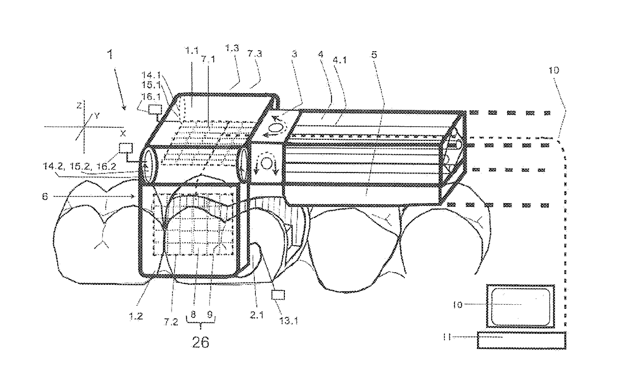
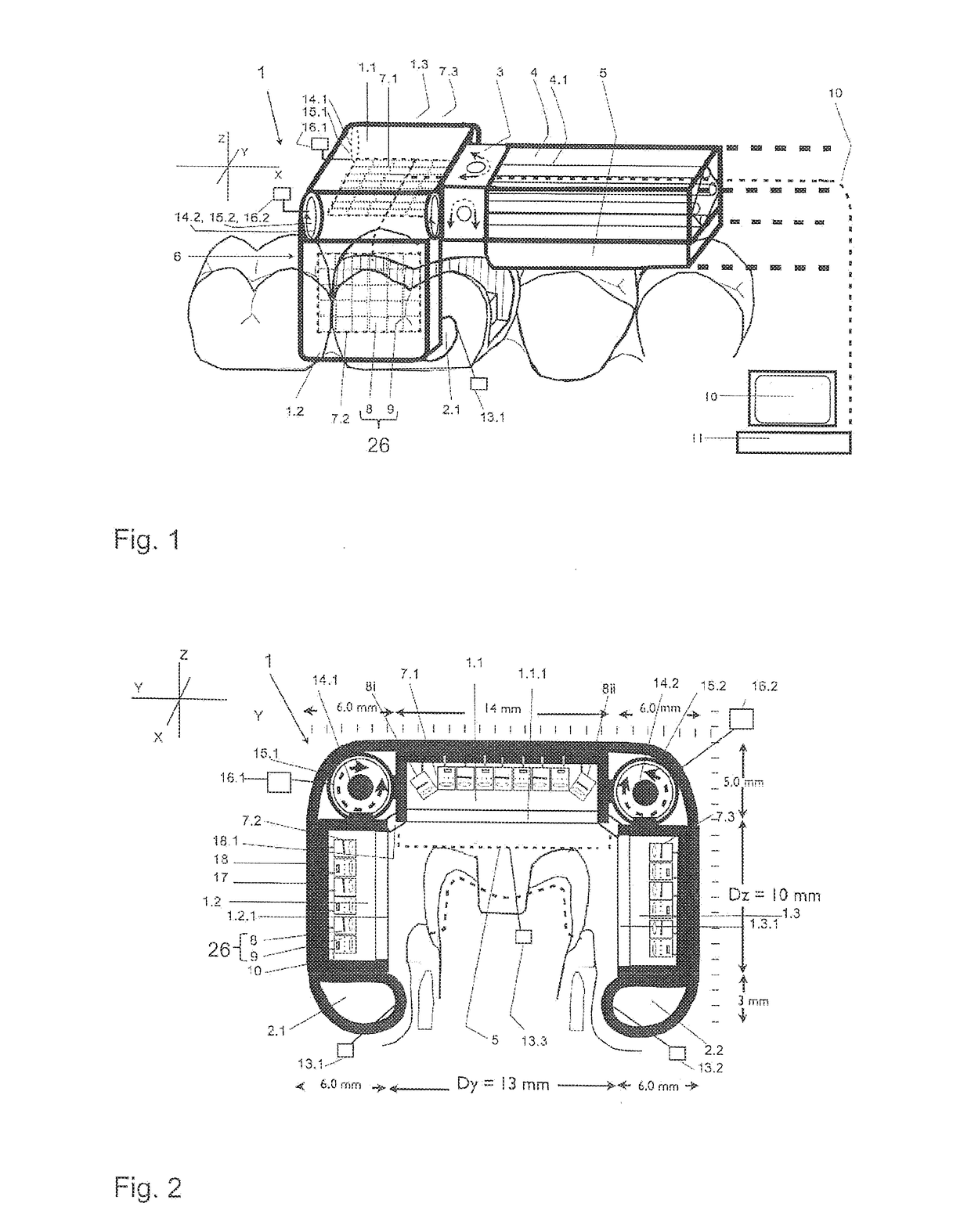
[0100]FIG. 1 shows the embodiment of a measuring apparatus in which a measuring head 1 is connected by a tilting actuator 3 movably with a shaft 4. The measuring head 1 comprises a central measuring member 1.1 and two lateral, pivotingly attached measuring members 1.2, 1.3. For contact with the row of teeth the measuring members 1.1, 1.2, 1.3 feature guiding members 2.1, 2.2, and the shaft 4 is equipped with a support 5 to provide support on the row of teeth. The apparatus is presented schematically in perspective side view above the row of teeth.

[0101]The guiding members 2.1, 2.2 are arranged at the free ends of the lateral measuring members 1.2, 1.3 and extend along the axis X.

[0102]The measuring members 1.1, 1.2, 1.3 together form the carrier for the measuring units described further down.

[0103]With the tilting actuator 3 the carrier 1.1-1.3 can be tilted automatically with respect to the support 5.

[0104]The measuring head 1 defines, based on its orientat...


PUM


Abstract

Disclosed is a measuring apparatus for three-dimensionally measuring a row of teeth, the rows of teeth of the maxilla and mandible, buccally, during articulation and during terminal occlusion, an alveolar ridge or the palate in the oral cavity, the measuring apparatus comprising an autonomously movable measuring head (1) on a shaft (4), said measuring head (1) consisting of a central measuring member (1.1) and at least two lateral measuring members (1.2, 1.3) which are movably interconnected and define a variable measurement space (6). The measuring head (1) can be placed on the row of teeth and is be guided therealong using guiding elements (1.1.1, 2.1, 2.2, 5); contact sensors (13) and angle sensors (16) ensure that the lateral measuring members are laterally guided and the angles thereof are adjusted to the topology of the alveolar ridge while the central guiding element (1.1.1) and/or a support (5) of the shaft (4) can rest on the row of teeth. Measuring units (26) for measuring the structures in the measurement space (6) are provided in the measuring members (1.1, 1.2, 1.3). Measurements are taken from multiple solid angle positions of the measuring units, said positions being preset in the measuring members (1.1, 1.2, 1.3), being adjusted by moving the measuring members (1.1, 1.2, 1.3), being taken by having mirrors move, in a controlled manner, the beam path generated by the measuring units, or being aligned by changing the angular position of the measuring head (1) relative to the shaft (4) in an automatically controlled manner.

Description

FIELD OF THE INVENTION[0001]The invention relates to a measuring apparatus for measuring at least a part of an oral cavity, in particular of at least a part of a row of teeth, as well as a corresponding method.BACKGROUND[0002]An overview of current intraoral 3D-camera systems is found in Int J Comput Dent 2013; 16: 143-162. The cameras described there use an endoscope-type design with a camera body and an access shaft into the mouth, which has an optical window or projectors and sensors at its end. For serial recordings, these cameras are guided freehanded and floating or supported over the row of teeth. According to experience, these known scanners are suited for the measurement of partial rows of teeth.[0003]Application problems exist with scanners of this type when acquiring data from poorly visible surface parts, e.g. for interdental to mesial or distal-oriented natural tooth surfaces as well as for fine-detailed, partly vertical geometrical preparation surfaces. This applies al...

Claims


Application Information

Patent Timeline
IPC IPC(8): A61C9/00A61B1/24
CPCA61C9/008A61C9/006A61B1/24A61C9/0073A61C9/0066A61C9/0053
Inventor MORMANN, WERNERMEHL, ALBERT
Owner QUARZ PARTNERS
Why Eureka
Try Eureka