Dynamic strain distributed fiber optic sensor

a fiber optic sensor and dynamic strain technology, applied in the field of physical characteristics measurement, can solve the problems of only 5 cm long vibrating section, amplification of the pump, loss of the probe, etc., and achieve the effect of shortening the measurement tim

Inactive Publication Date: 2009-01-20
UNIVERSITY OF NEW BRUNSWICK
View PDF2 Cites 25 Cited by
  • Summary
  • Abstract
  • Description
  • Claims
  • Application Information

AI Technical Summary

Benefits of technology

[0031]The present invention teaches an improved method of distributed sensing with Brillouin scattering that allows for significantly shorter measurement times, thereby providing the capability to monitor dynamic processes.
[0032]The present invention provides a distributed fiber optic based sensor system using Brillouin scattering that overcomes the previously described limitations of all known systems that use the Brillouin scattering process by allowing for rapid measurements of the Brillouin spectrum using a single pass of light through the fiber.
[0033]This invention employs a novel technique for simultaneously interrogating the sensing fiber with two counter propagating light beams. One beam is set to a constant frequency, consistent with prior art. The second beam is modified to contain a “comb” of frequencies, with each frequency component in the comb offset by a predetermined amount. Each of the frequency components in the comb, herein referred to as teeth, is able to interact with the counter-propagating beam through the Brillouin scattering process. With proper selection of the comb characteristics such as the number of teeth, the frequency spacing of teeth, the spectral width of teeth, and the relative amplitude of the teeth, a representation of the Brillouin spectrum at each point in the fiber can be obtained simultaneously with a single pass through the fiber. The use of a comb of frequencies eliminates the need for the slow process of sequentially stepping through a range of frequencies using a distinct pass of light through the fiber at each frequency. The use of a comb of frequencies allows the interrogation process to occur at many different frequencies simultaneously. This innovation significantly reduces the time required to measure the Brillouin spectrum for any length of sensing fiber. In this way, a system for rapidly collecting distributed measurements from fiber optic cable results.
[0040]A further object is to provide a means of rapidly measuring the Brillouin scattering spectrum with a single pass of light through the optical fiber.
[0041]A further object is to provide a means of rapidly measuring the Brillouin scattering spectrum through the use of a light beam modified to contain to a comb of frequency components.

Problems solved by technology

As a result, the pump experienced amplification and the probe experienced loss.
Gas pipelines are several hundred km long and sometimes they are damaged by construction equipment like boring and drilling machines.
However, this system should be able to distinguish between vibrations caused by normal conditions like an overhead passing train, lawn mowing etc. and potentially hazardous equipment.
However, the vibrating section was only 5 cm long.
The use of a sequential, iterative procedure for varying the frequency difference results in a time-consuming measurement process.
In situations where dynamic measurements are required, such as for monitoring vibrations, the previously described methods that exist in the prior art are not able to provide sufficiently rapid measurement rates.
Although this technique offers dynamic measurement capabilities, it suffers from several limitations.
This process often degrades said fiber's mechanical strength and increases the overall cost of the length of sensing fiber.
Second, there are practical limits to the total number of FBG sensors that can be applied to the sensing fiber.
This limitation can reduce the maximum length of sensing fiber and can result in large distances between discrete FBG sensing points.

Method used


Image

  • Dynamic strain distributed fiber optic sensor
  • Dynamic strain distributed fiber optic sensor
  • Dynamic strain distributed fiber optic sensor

Examples


Embodiment Construction

[0097]A preferred embodiment of the present invention and modifications thereof will be set forth in detail with reference to the drawings, in which like reference numerals refer to like elements or steps throughout.

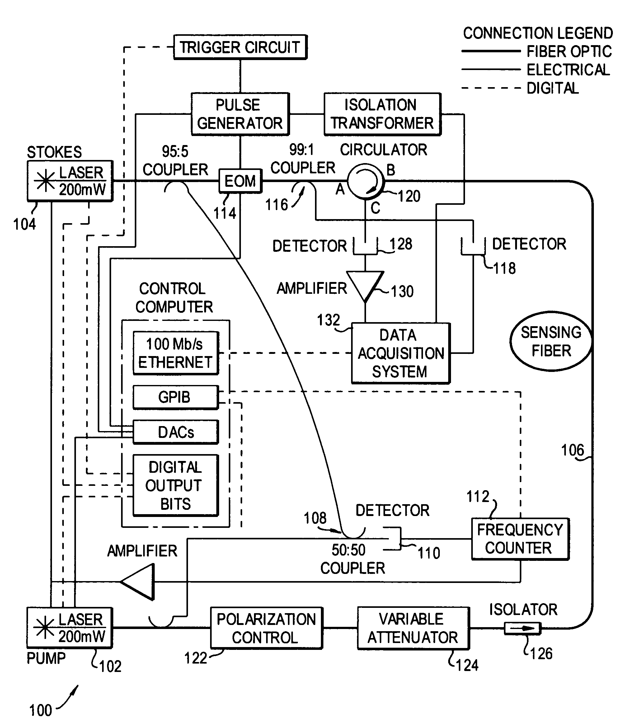
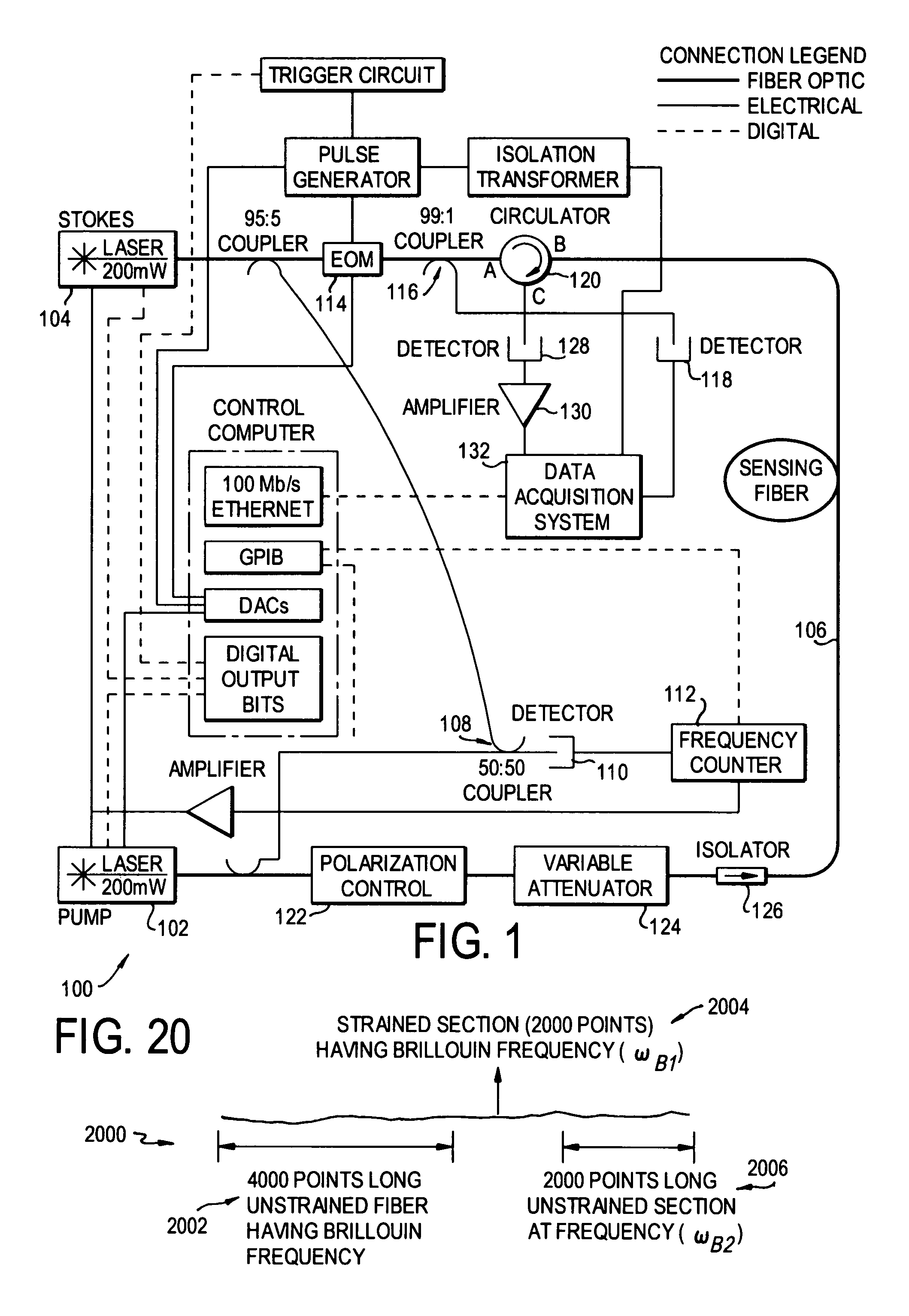
[0098]The sensor system according to the preferred embodiment is based on the principle of Brillouin loss mechanism. The overall system diagram is shown in FIG. 1 as 100. The Nd:YAG lasers 102, 104 operate at 1319 nm. The pulsed light from the pump laser 102 enters one end of the fiber 106, and the cw light from the probe laser 104 enters the other end of the fiber. The frequency difference is varied over a range of values to cover the entire Brillouin spectrum on each point on the fiber. The entire system is automated using software called NTControl which automatically changes the frequency and acquires the data. NTControl is user friendly software having a window in which 35 settings can be adjusted, the most important ones being the fiber start, fiber end, time base, ...


PUM


Abstract

A distributed fiber optic sensor simultaneously interrogates the sensing fiber with two counter propagating light beams. One beam is set to a constant frequency. The second beam is modified to contain a “comb” of frequencies, with each frequency component in the comb offset by a predetermined amount. Each of the frequency components in the comb, herein referred to as teeth, is able to interact with the counter-propagating beam through the Brillouin scattering process. With proper selection of the comb characteristics such as the number of teeth, the frequency spacing of teeth, the spectral width of teeth, and the relative amplitude of the teeth, a representation of the Brillouin spectrum at each point in the fiber can be obtained simultaneously with a single pass through the fiber.

Description

REFERENCE TO RELATED APPLICATION[0001]The present application claims the benefit of U.S. Provisional Patent Application No. 60 / 665,860, filed Mar. 29, 2005, whose disclosure is hereby incorporated in its entirety into the present application.FIELD OF THE INVENTION[0002]The present invention is directed to a method of measuring physical characteristics, particularly but not exclusively strain, displacement and temperature, and in particular a method based on the measurement and analysis of the Brillouin scattering spectrum in optical fiber. The present invention is further directed to a distributed fiber optic sensing system for use in rapidly measuring such physical characteristics at a fast measurement rate.DESCRIPTION OF RELATED ART[0003]The use of fiber optic technology for sensing environmental and structural properties is well known in many industries where it provides meaningful information to help ensure safety and efficiency of operation. Fiber optic sensors can be deployed ...

Claims


Application Information

Patent Timeline
Patent Type & Authority Patents(United States)
IPC IPC(8): H04B10/00
CPCG01B11/16G01D5/35364G01K11/32
Inventor COLPITTS, BRUCE G.BROWN, ANTHONY W.
Owner UNIVERSITY OF NEW BRUNSWICK
Why Eureka
Try Eureka