Actuatable Assemblies Fabricatable by Deposition of Solidifying and Non-Solidifying Materials

a technology of solidifying materials and assemblies, applied in the field of actuatable assemblies, can solve the problems of relatively few opportunities for automating assembly, difficult and costly small changes, and time-consuming process of building robots, and achieve the effects of reducing manufacturing lead-times, reducing manufacturing costs, and eliminating most or all assembly steps

Inactive Publication Date: 2017-05-04
MASSACHUSETTS INST OF TECH
View PDF6 Cites 28 Cited by
  • Summary
  • Abstract
  • Description
  • Claims
  • Application Information

AI Technical Summary

Benefits of technology

[0016]Embodiments disclosed herein extend the capabilities of multi-material 3D printing by incorporating a material that does not solidify into a material palette, thereby permitting manufacture of structures that allow force-transfer throughout an assembly via hydraulic pressure.
[0017]Embodiments of the method described herein provide a number of advantages. Since 3D printers can produce arbitrary geometries with multiple materials simultaneously, individual components can be co-fabricated in-situ, eliminating most or all assembly steps. This transforms the design space: complexity becomes free, once the 3D printer has been purchased, because incremental increases in design complexity do not require increases in fabrication complexity. Similarly, 3D printing makes the incremental cost of variety very low, allowing components to be diversified and specialized in an individual robot or across a suite of robots. Additionally, 3D printing reduces fabrication lead-times to zero, removes requirements for operator skill, and frees designers from most constraints imposed by the reachable space of the machine tool.

Problems solved by technology

Building robots has historically been a time-consuming process.
Constrained by available fabrication techniques, conventional robotic design practice requires sequential assembly from many discrete parts, with long concomitant assembly times. Mass-production achieves efficiency gains through optimizing each assembly step, but optimization requires that the design be fixed; even small changes become difficult and costly.
Additionally, because many robots are unique or application-specific, relatively few opportunities to automate their assembly exist.
This situation is worsened by inevitable design-fabricate-test-redesign iterations.
For example, a stamping press with a die customized for a particular part can rapidly produce many identical copies of that part, but slight design modifications to the part require costly and time-consuming changes to the die.
In contrast, a computer numerical control (CNC) milling machine with interchangeable tools can easily accommodate design changes, but is slower than stamping, is constrained by the reachable space of its tooling, and cannot readily create parts with heterogeneous structure.

Method used


Image

  • Actuatable Assemblies Fabricatable by Deposition of Solidifying and Non-Solidifying Materials
  • Actuatable Assemblies Fabricatable by Deposition of Solidifying and Non-Solidifying Materials
  • Actuatable Assemblies Fabricatable by Deposition of Solidifying and Non-Solidifying Materials

Examples


Embodiment Construction

[0032]A description of example embodiments of the invention follows.

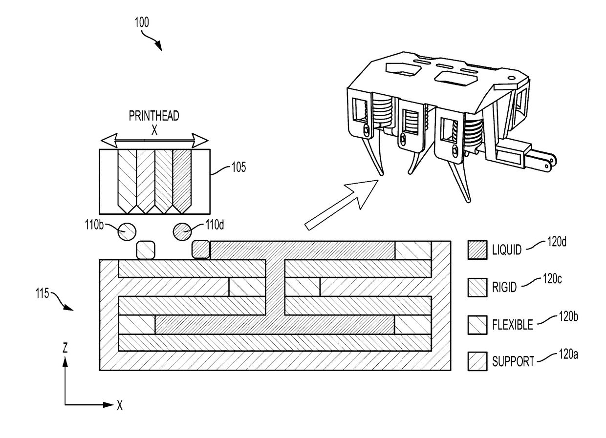
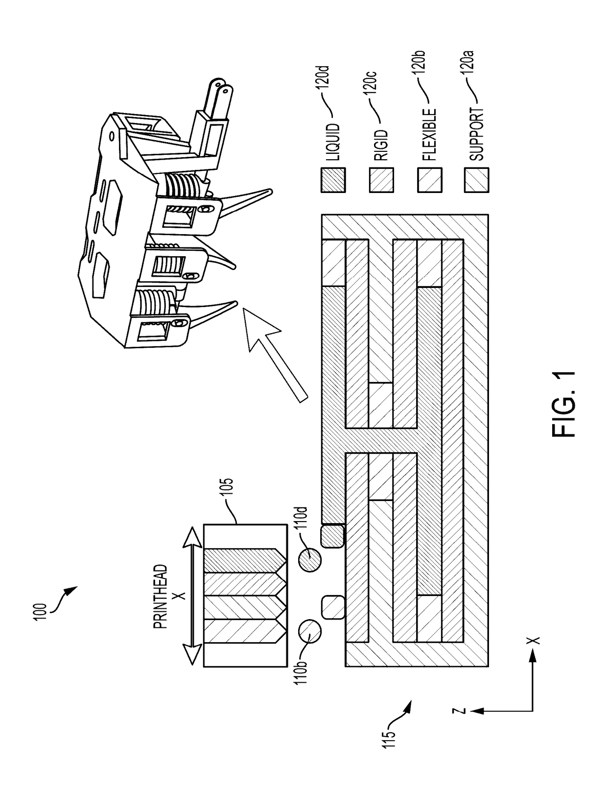
[0033]Multi-material additive manufacturing techniques offer a compelling alternative fabrication approach compared to conventional fabrication techniques, allowing materials with diverse mechanical properties to be placed at arbitrary locations within a structure, and enabling complex multi-part design iterations to be rapidly fabricated with trivial effort.

[0034]3D printers have been demonstrated with a variety of model materials, ranging from ice to nylon to cookie dough. However, non-solidifying materials have not been widely used as either model or support material. The role of support material in 3D printers is to provide a platform for overhanging geometries on subsequent layers during bottom-up, layer-by-layer fabrication; weak solidifying materials that can be washed away or dissolved are typically used as support. A related approach uses wax as a support material; the wax hardens soon after deposition and ...


PUM

PropertyMeasurementUnit
diameteraaaaaaaaaa
drive voltageaaaaaaaaaa
thickaaaaaaaaaa

Abstract

Actuatable assemblies fabricated by deposition of solidifying and non-solidifying materials are described herein. The actuable assemblies can be formed by co-deposition of a solidifying material and a non-solidifying material.

Description

RELATED APPLICATION[0001]This application claims the benefit of U.S. Provisional Application No. 62 / 250,006, filed on Nov. 3, 2015. The entire teachings of the above application are incorporated herein by reference.GOVERNMENT SUPPORT[0002]This invention was made with Government support under Grant Nos. U.S. Pat. No. 1,226,883 and CCF-1138967 awarded by the National Science Foundation. The Government has certain rights in the invention.BACKGROUND[0003]Building robots has historically been a time-consuming process. Constrained by available fabrication techniques, conventional robotic design practice requires sequential assembly from many discrete parts, with long concomitant assembly times. Mass-production achieves efficiency gains through optimizing each assembly step, but optimization requires that the design be fixed; even small changes become difficult and costly. Additionally, because many robots are unique or application-specific, relatively few opportunities to automate their a...

Claims


Application Information

Patent Timeline
Patent Type & Authority Applications(United States)
IPC IPC(8): B29C67/00B33Y50/02B33Y80/00B33Y10/00
CPCB29C67/0092B29C67/007B29C67/0088B29K2105/0058B33Y50/02B33Y80/00B33Y10/00B29C64/112B29C64/40B29C64/336
Inventor MACCURDY, ROBERT BRUCERUS, DANIELA
Owner MASSACHUSETTS INST OF TECH
Why Eureka
Try Eureka