Bearing for supporting a shaft, in particular a rudder shaft, or a rudder blade, electronic bearing clearance measuring device, rudder comprising a bearing for supporting a shaft or a rudder blade, and method for measuring wear of a bearing for supporting a shaft or a rudder blade

a technology for supporting shafts and bearings, which is applied in the direction of bearings, steering components, shafts, etc., can solve the problems of structural weakening of the outer bearing portion, the risk of damage to the wear pin, and the inability to reliably measure bearing wear

Inactive Publication Date: 2017-05-04
BECKER MARINE SYST
View PDF0 Cites 14 Cited by
  • Summary
  • Abstract
  • Description
  • Claims
  • Application Information

AI Technical Summary

Benefits of technology

[0016]If the new measurand sensor is not pin-shaped, wherein it can indeed have a substantially elongate design, although the wear surface is then not substantially perpendicular or transverse to the longitudinal axis of the measurand sensor, but instead is preferably oriented substantially parallel to the longitudinal axis of the measurand sensor, the measurand sensor can thus be brought via the wear surface into sliding contact with the second bearing element, in such a way that the longitudinal axis is not perpendicular to the second bearing element. The risk of damage to the measurand sensor as a result of friction and shearing forces occurring with sliding contact of the measurand sensor against the second bearing element is thus advantageously reduced.
[0076]In accordance with a further advantageous embodiment, the rudder is characterised in that a spacer formed preferably as a clamping ring is provided, and in that the spacer preferably can be attached to the inner side of the trunk pipe in such a way that damage to the measurand sensor during the insertion of the rudder shaft into the trunk pipe of the rudder trunk can be avoided.

Problems solved by technology

This gives rise in the aforementioned prior art to the problem that the known wear pin is vulnerable with respect to shear forces and thus there is a risk of damage to the wear pin as a result of friction and shearing forces occurring with sliding contact of the wear pin against an inner bearing portion.
Furthermore, there is the problem that the wear pin arranged in the through-hole can have play therein, in particular radial play, which may mean that the wear pin is not continuously arranged slidingly on the inner bearing portion, and bearing wear cannot be reliably measured.
Further, due to the relatively large dimensions of the through-hole, as this has to receive the wear pin, a structural weakening of the outer bearing portion can occur.

Method used


Image

  • Bearing for supporting a shaft, in particular a rudder shaft, or a rudder blade, electronic bearing clearance measuring device, rudder comprising a bearing for supporting a shaft or a rudder blade, and method for measuring wear of a bearing for supporting a shaft or a rudder blade
  • Bearing for supporting a shaft, in particular a rudder shaft, or a rudder blade, electronic bearing clearance measuring device, rudder comprising a bearing for supporting a shaft or a rudder blade, and method for measuring wear of a bearing for supporting a shaft or a rudder blade
  • Bearing for supporting a shaft, in particular a rudder shaft, or a rudder blade, electronic bearing clearance measuring device, rudder comprising a bearing for supporting a shaft or a rudder blade, and method for measuring wear of a bearing for supporting a shaft or a rudder blade

Examples


Embodiment Construction

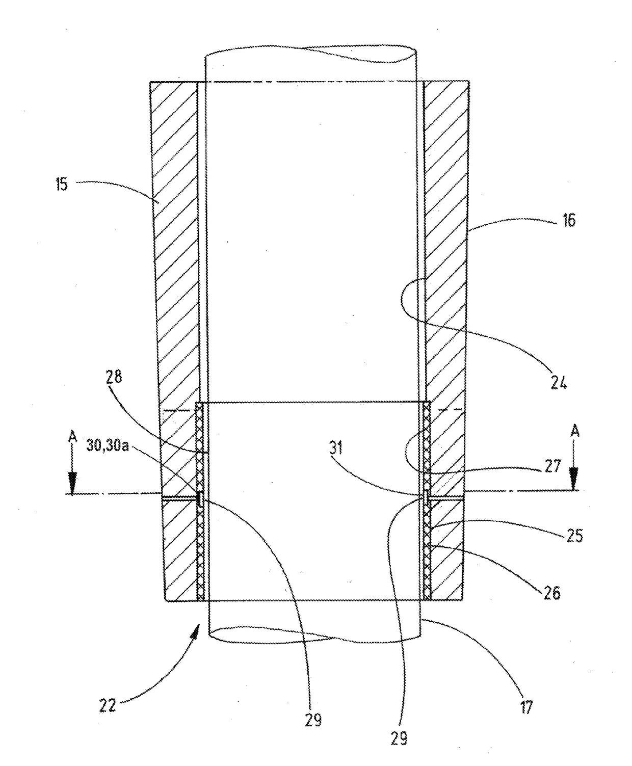
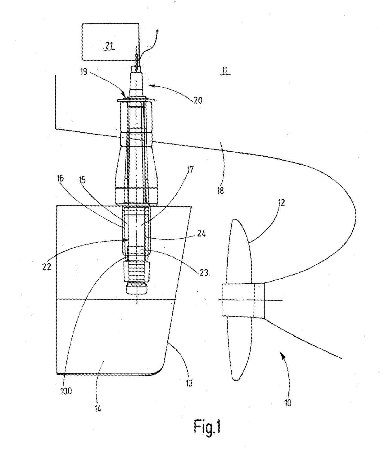
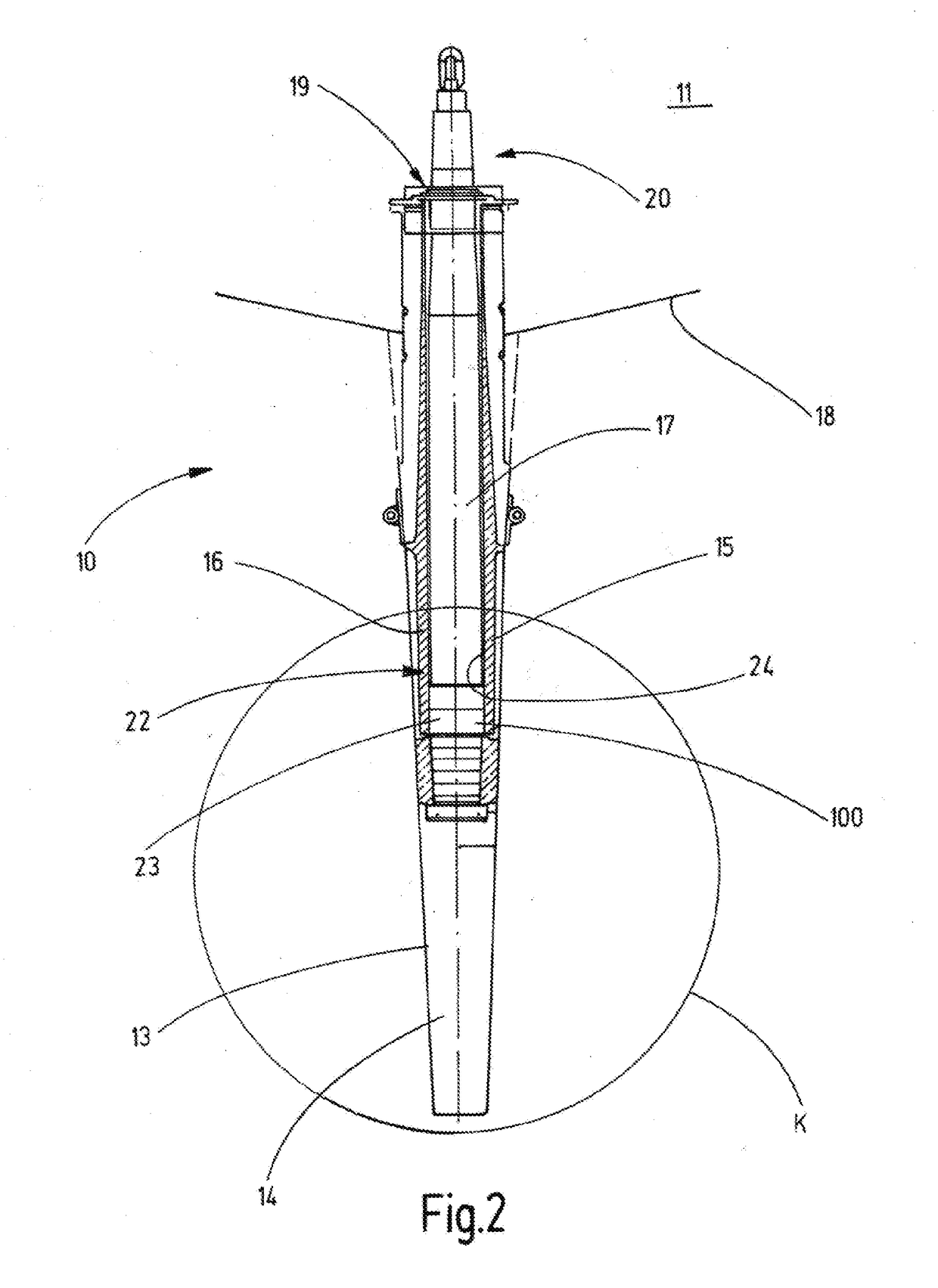
[0097]FIGS. 1 and 2 show the stern 10 of a ship 11 comprising a bearing 100 for supporting a rudder shaft in a side view and in a rear view. Behind a propeller 12, as viewed in the direction of travel, there is arranged a rudder 13 comprising a rudder blade 14. In FIG. 2 the propeller is indicated by the propeller circle K, over which the propeller blades travel. The rudder blade 14 is arranged on a rudder shaft 17 mounted rotatably in a trunk pipe 15 of a rudder trunk 16. The rudder shaft 17 is drawn deep into the rudder blade 14. The trunk pipe 15 of the rudder trunk 16 is fixedly connected to the ship's hull 18. In a vertical direction, the rudder shaft 17 is secured above the trunk pipe 15 by means of a supporting bearing 19 formed as an axial bearing. The rudder shaft 17 is connected via an upper end region 20 to a rudder engine 21. The rudder shaft 17 is supported on the trunk pipe 15 of the rudder trunk 16 via a journal bearing 23 arranged at a lower end region 22 of the rudd...


PUM


Abstract

The invention relates to a bearing for supporting a shaft, in particular a rudder shaft, or a rudder blade, by means of which bearing the bearing clearance or the bearing wear can be continuously monitored, determined, and optionally documented. According to the invention, for a bearing for supporting a shaft, in particular a rudder shaft, comprising a first bearing element and a second bearing element, wherein the first bearing element has a sliding surface for contacting the second bearing element in a sliding manner, and a measurement-value sensor having a wear surface for contacting the second bearing element in a sliding manner, the at least one measurement-value sensor is not pin-shaped.

Description

[0001]The invention relates to a bearing for supporting a shaft or a rudder blade, comprising a first bearing element and a second bearing element, wherein the first bearing element has a sliding surface for contacting the second bearing element in a sliding manner, and a measurand sensor having a wear surface for contacting the second bearing element in a sliding manner. The invention also relates to a bearing clearance measuring device, a rudder comprising a bearing for supporting a shaft or a rudder blade, and a method for measuring the wear of a bearing for supporting a shaft or a rudder blade.[0002]In the case of large rudders, for example for container ships, it is known that the rudder shaft is introduced far into the interior of the rudder blade by means of a rudder trunk, when the rudder is designed as a full spade rudder. In general, the rudder shaft at the free end of the rudder trunk is mounted in a journal bearing which is arranged between the rudder trunk and rudder sh...

Claims


Application Information

Patent Timeline
Patent Type & Authority Applications(United States)
IPC IPC(8): F16C17/24G01B7/14F16C17/02B63H25/52B63H25/38
CPCF16C17/246B63H25/52B63H25/38F16C2326/30G01B7/144F16C2233/00F16C17/02G01B21/16G01M13/04G01N3/56G01B5/146
Inventor KUHLMANN, HENNINGSELIGER, LEIF
Owner BECKER MARINE SYST
Why Eureka
Try Eureka