
Free-form display

a display and free-form technology, applied in the field of display, can solve the problems of not being suitable for display having specific or free-form shapes, rectangular displays are typically not suitable for display for wall clocks, wristwatches, dead zones where no image is displayed,

Active Publication Date: 2017-05-04
LG DISPLAY CO LTD
View PDF0 Cites 21 Cited by
  • Summary
  • Abstract
  • Description
  • Claims
  • Application Information

AI Technical Summary

Benefits of technology

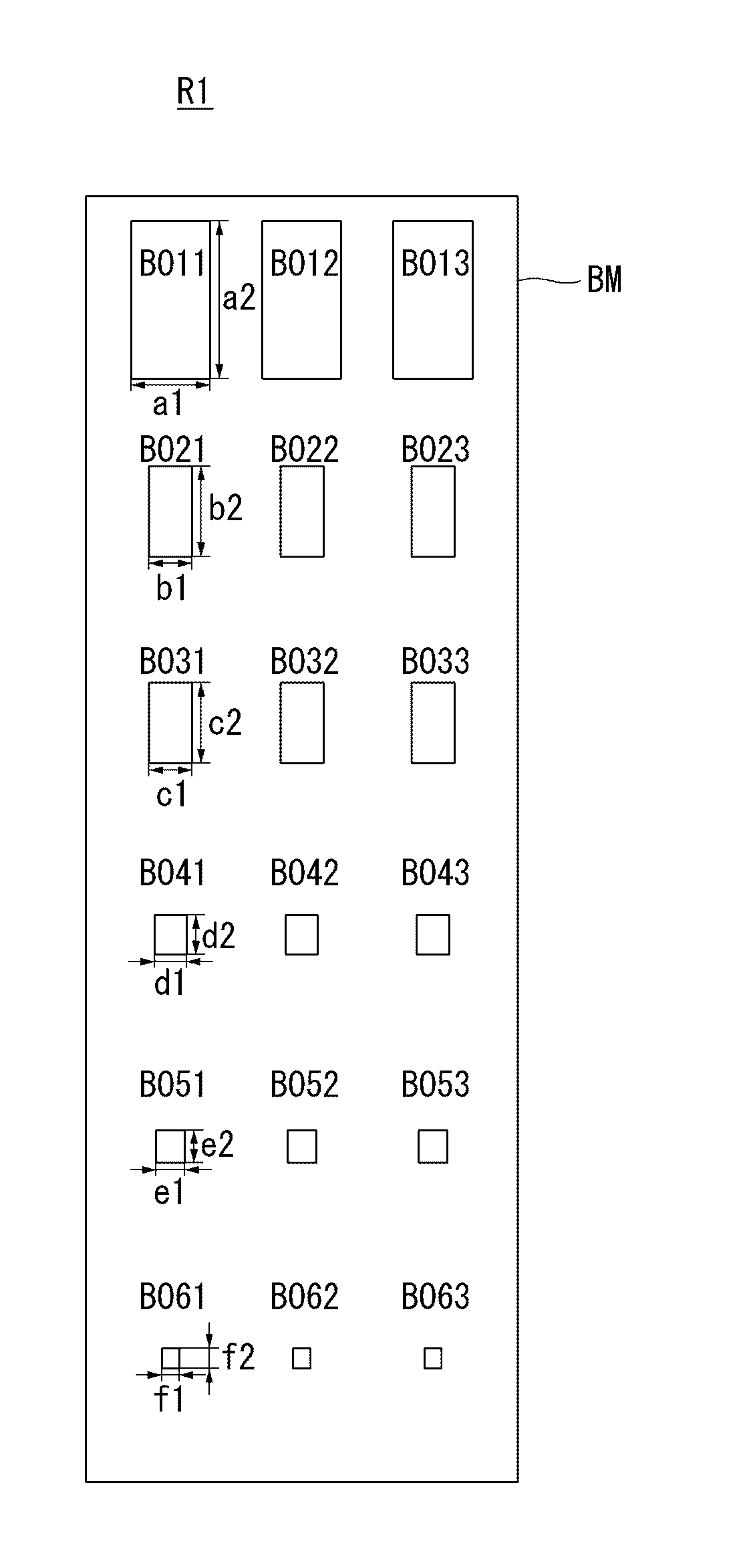
The present invention provides a free-form display with a less visible step-like pattern. This is achieved by a display having a free-form boundary between the active area and the bezel area, where a plurality of subpixel electrodes are arranged. A light blocking portion is provided with openings exposing the subpixel electrodes and is arranged to overlap the gate lines and data lines. The openings in the light blocking portion adjacent to non-pixel areas are made in different sizes, while the openings in the adjacent pixel areas are changed in size proportionately according to gamma characteristics. This results in a less visible step-like pattern and better display quality.

Problems solved by technology

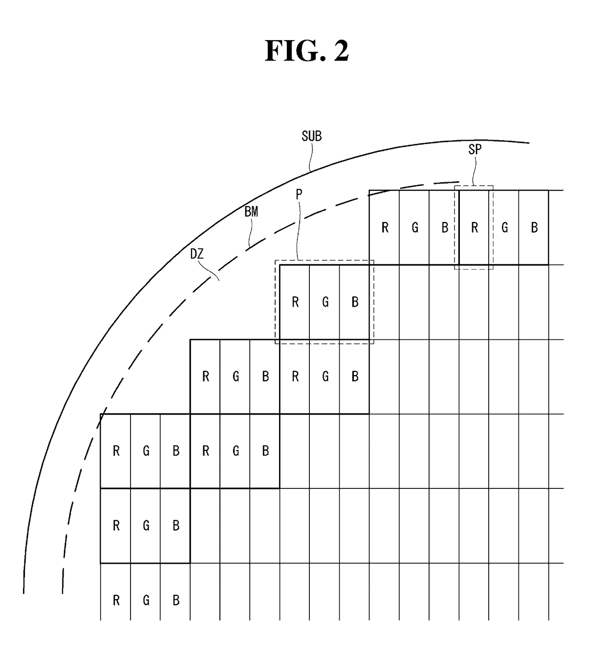
However, these flat panel display have been developed for large screens with a rectangular display panel for displaying images, and thus, are typically not suitable for displays having specific or free-form shapes.
For example, rectangular displays are typically not suitable for displays for wall clocks, wristwatches, and dashboards, for example, which have a variety of shapes like circles, ellipses, or diagonals.
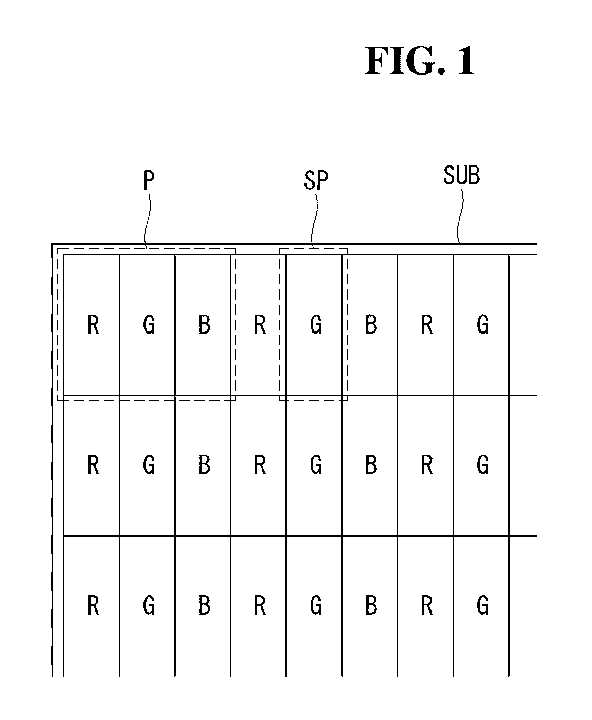
That is, no pixels are placed in between the outermost pixels P of a data display area and the outline of the substrate SUB, which results in a dead zone where no image is displayed.

Method used


Image

  • Free-form display
  • Free-form display
  • Free-form display

Examples


Embodiment Construction

[0036]Hereinafter, exemplary embodiments of the present invention will be described in detail with reference to the accompanying drawings. Throughout the specification, the same reference numerals indicate substantially the same components. In describing the present invention, when it is deemed that a detailed description of known functions or configurations may unnecessarily obscure the subject matter of the present invention, the detailed description will be omitted.

[0037]Hereinafter, a free-form display according to an exemplary embodiment of the present invention will be described with reference to FIGS. 3 to 5B.

[0038]FIG. 3 is a top plan view schematically showing a free-form display and a free-form portion according to an exemplary embodiment of the present invention. FIG. 4 is an enlarged top plan view showing the region R1 of FIG. 3. FIG. 5A is a top plan view showing the pixel electrodes of FIG. 4. FIG. 5B is a top plan view showing the black matrix of FIG. 4.

[0039]Referrin...


PUM


Abstract

A free-form display is disclosed which makes a step-like pattern adjacent to a free-form portion less visible. The free-form display has an active area and a bezel area, and at least part of a boundary between the active area and the bezel area has a free-form portion. The free-form portion comprises subpixel electrodes and a light blocking portion. A plurality of subpixel electrodes are placed in areas defined by a plurality of gate lines and a plurality of data lines that intersect each other. A light blocking portion has openings exposing the subpixel electrodes, respectively, and is arranged to overlap the gate lines and the data lines. The active area comprises subpixel areas where the subpixel electrodes are placed, and a non-pixel area where no subpixel electrodes are placed. The openings of the light blocking portion adjacent to the non-pixel area, are made in different sizes.

Description

[0001]This application claims the benefit of priority under 35 U.S.C. §119(a) to Republic of Korea Patent Application No. 10-2015-0151794 filed on Oct. 30, 2015, the entire contents of which are incorporated herein by reference for all purposes as if fully set forth herein.BACKGROUND OF THE INVENTION[0002]Field of the Invention[0003]The present invention relates to a display and a method of manufacturing the same, and more particularly, to a free-form display.[0004]Discussion of the Related Art[0005]With the development of the information society, various demands for display devices for displaying images are on the rise. In the field of display devices, flat panel displays (FPDs), which are thin and light and can cover a large area, have been rapidly replacing cathode ray tubes (CRTs), which are bulky. For example, a variety of flat panel displays have been developed and used, including liquid crystal displays (LCDs), plasma display panels (PDPs), organic light-emitting displays (OL...

Claims


Application Information

Patent Timeline
Patent Type & Authority Applications(United States)
IPC IPC(8): H01L27/12H01L29/786
CPCH01L27/1218H01L29/78633H01L27/124G09F9/30G09F9/35G09F9/335G09F9/313H10K59/8792G02F1/133512G02F2201/56G09G2300/0465H10K59/352G02F1/134309H10K50/865
Inventor PARK, CHANSOOLEE, SEEUNGRYOO, SEUNGSEOK
Owner LG DISPLAY CO LTD
Learn More