Eureka AIR delivers breakthrough ideas for toughest innovation challenges, trusted by R&D personnel around the world.

Brush Head for an Electrically Driven Toothbrush

a toothbrush head and toothbrush head technology, applied in the field of toothbrush head for electrically driven toothbrushes, can solve the problems of difficult cleaning of buccal tooth surfaces anyway, and the general inability of plastic materials to be used in inmolding methods

Active Publication Date: 2017-05-11
M C SCHIFFER
View PDF3 Cites 21 Cited by
  • Summary
  • Abstract
  • Description
  • Claims
  • Application Information

AI Technical Summary

Benefits of technology

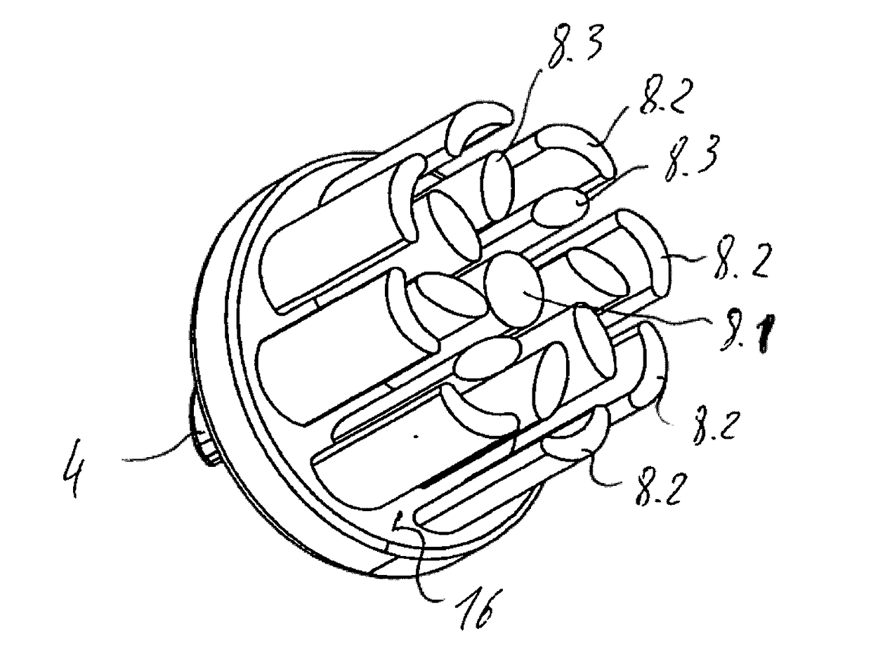
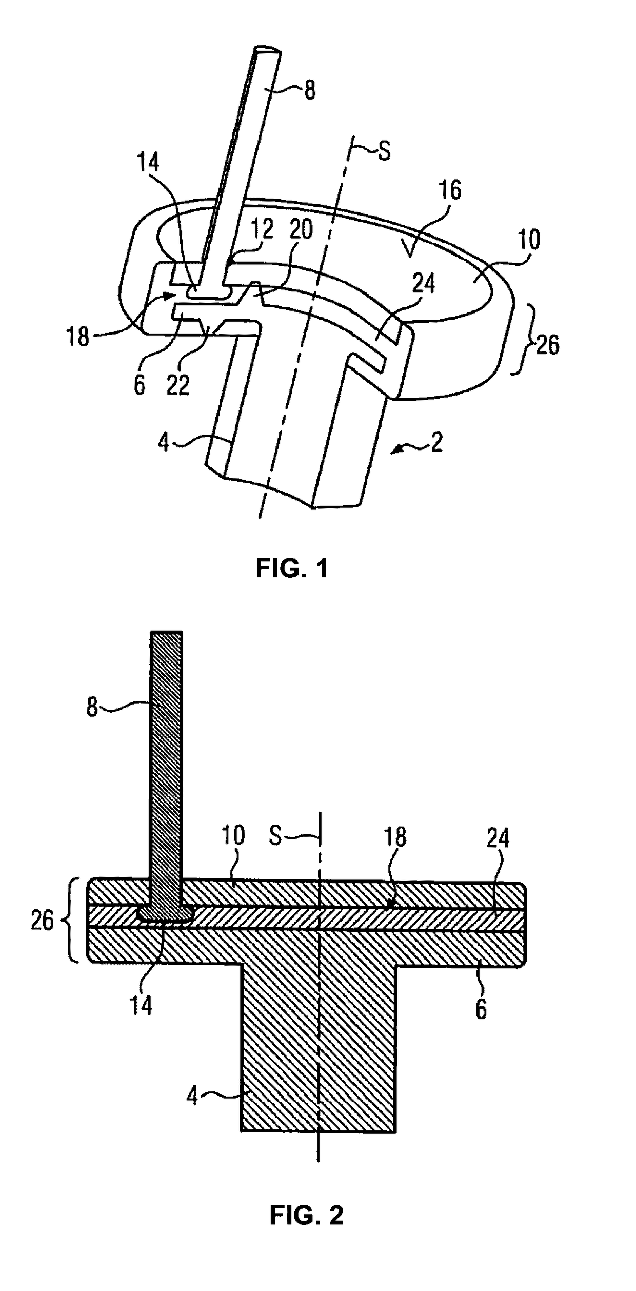
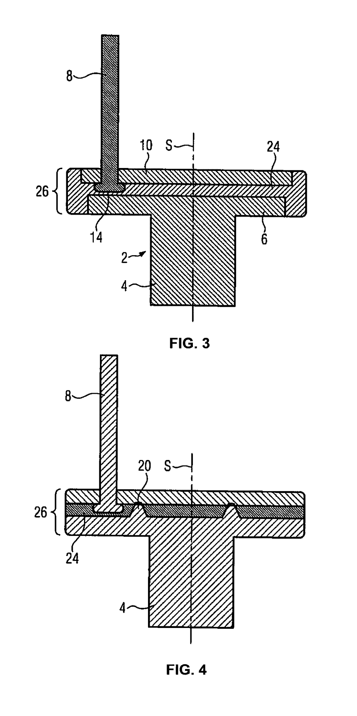
The present invention proposes a brush head for an electrically driven toothbrush that can mechanically couple to the electric drive of the toothbrush. The brush head has a holding part that provides at least one connecting element for mechanically coupling the brush head to the electric drive of the toothbrush. The holding part has a stud that defines a pivot axis of the brush head. The brush head can perform a rotational or pivotal motion relative to the sleeve member but is captive coupled to the sleeve member. The connecting element is a receptacle in which the drive shaft of the attachment part engages. The brush head also has a centrical stud that is radially protruded by a plate. The brush head also comprises a disc-shaped bristle carrier and a thickening formed on the rear side of the bristle carrier to secure the bristle bundle in place. The brush head also has nubs that serve to position the plate in an injection mold. The invention provides a solution for securely attaching the brush head to the electric drive of the toothbrush.

Problems solved by technology

Cleaning elements for the oral cavity are generally subject to the demand of having them be designed very compact and in space-saving manner since the space in the oral cavity is limited, where cleaning buccal tooth surfaces is difficult anyway due to the cheek being in the immediate vicinity.
Technical plastic materials are generally not suitable for the Inmold Method due to their high viscosity under processing conditions.

Method used


Image

  • Brush Head for an Electrically Driven Toothbrush
  • Brush Head for an Electrically Driven Toothbrush
  • Brush Head for an Electrically Driven Toothbrush

Examples


Embodiment Construction

[0036]The figures each schematically illustrated the embodiments. Reference numeral 2 denotes a holding part which forms a stud 4 and a plate 6 protruding radially therefrom and provided integrally on the stud 4. A bristle bundle 8 penetrates a bore 12 provided in a bristle carrier 10 and with its thickening 14 abuts at the rear side of the bristle carrier 10 against the latter. To simplify the illustration, only one bristle bundle 8 is shown in FIG. 1. It goes without saying that the entire surface 16 being formed by the bristle carrier 10 is protruded by bristle bundles or other cleaning elements, for example, TPE cleaning elements, in order to achieve a cleaning effect over the entire surface. The bristle bundles and the cleaning elements can have different diameters, colors, material properties and contours as well as different bristle filaments and a different number of bristle filaments, as is customary in the market. Suitable cleaning elements are, in particular, TPE cleaning...


PUM

PropertyMeasurementUnit
outer diameteraaaaaaaaaa
thicknessaaaaaaaaaa

Abstract

A brush head for an electrically driven toothbrush includes a holding part (2) that provides at least one connecting element for mechanically coupling the brush head to the electric drive of the toothbrush, wherein the holding part (2) integrally forms a stud (4) defining a pivot axis (S) about which the brush head is pivotable, and a plate (6) which at its end facing away from the stud (4) carries at least one bristle bundle (8) which at its attachment-side end includes a thickening (14) formed by surface melting. For improving the brush head, a substantially disc-shaped bristle carrier (10) is connected to a holding part (2) and includes a bore that is penetrated by the bristle bundle (8).

Description

CROSS REFERENCE TO RELATED APPLICATION[0001]This application claims priority to European Patent Application No. EP 15193697.8, filed on Nov. 9, 2015, which is hereby incorporated by reference as if set forth in its entirety herein.BACKGROUND OF THE INVENTION[0002]Field of the Invention[0003]The present invention relates to a brush head for an electrically driven toothbrush. Such a brush head is commonly sold as a component of an attachment part which can be connected to a handpiece of the electrically driven toothbrush that commonly accommodates the drive in itself. The attachment part is an expendable item and made from plastic material. The attachment part usually comprises a sleeve member which is penetrated by a drive shaft that can be connected to a drive shaft of the handpiece. Disposed at the free end of the sleeve member is commonly the brush head according to the present invention.[0004]Description of Related Art[0005]Cleaning elements for the oral cavity are generally subj...

Claims


Application Information

Patent Timeline
Patent Type & Authority Applications(United States)
IPC IPC(8): A61C17/22A46B9/04A46B5/00
CPCA61C17/222A46B9/04A46B5/0095A46B3/06A46B13/00A46B2200/1066A46B13/008
Inventor SCHMIDT, ERICBUCHHOLZ, ERWIN
Owner M C SCHIFFER
Why Eureka
Eureka Blog
Learn More