
Hair clipping device

a technology of hair clipping and comb attachment, which is applied in the direction of metal working apparatus, etc., can solve the problems of not only allowing the movement but also the hair clipping device, so as to facilitate the adjustment of the comb attachment in the different positions and improve the effect of hair clipping

Active Publication Date: 2017-05-11
KONINKLJIJKE PHILIPS NV
View PDF8 Cites 8 Cited by
  • Summary
  • Abstract
  • Description
  • Claims
  • Application Information

AI Technical Summary

Benefits of technology

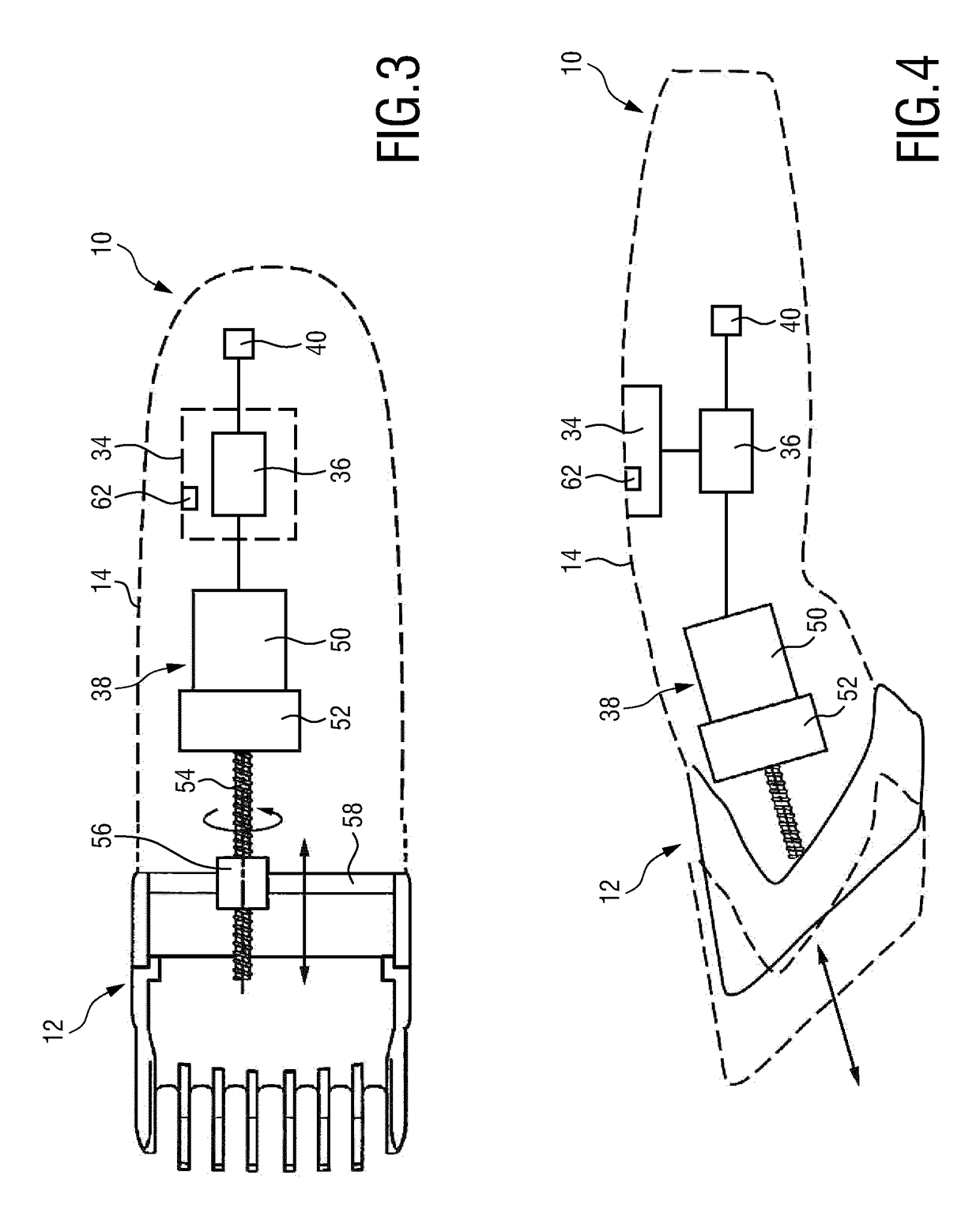
The present invention is a hair clipping device with an attachable comb attachment. The device has a memory function that allows the user to quickly change the comb position to their favorite length setting. The user only needs to recall the position information regarding the desired comb position from the memory unit by interacting with the user interface. The control unit will then automatically move the comb attachment to the desired position. This makes the device much more comfortable and quicker for the user. The user interface allows the user to easily control the memory function with only one button or input field. The device also adapts itself to different types of comb attachments, allowing the user to store multiple hair cut-length settings for each comb attachment.

Problems solved by technology

The presented hair clipping device, however, does not only allow moving the comb attachment between different comb positions “manually” by using a user interface which may include one or more buttons for controlling the drive unit, but also allows the user to store his / her favorite length settings and recall these length settings if needed.

Method used


Image

  • Hair clipping device
  • Hair clipping device
  • Hair clipping device

Examples


Embodiment Construction

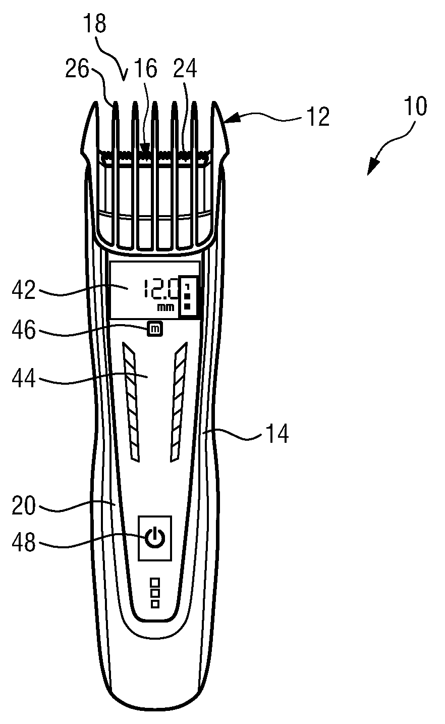
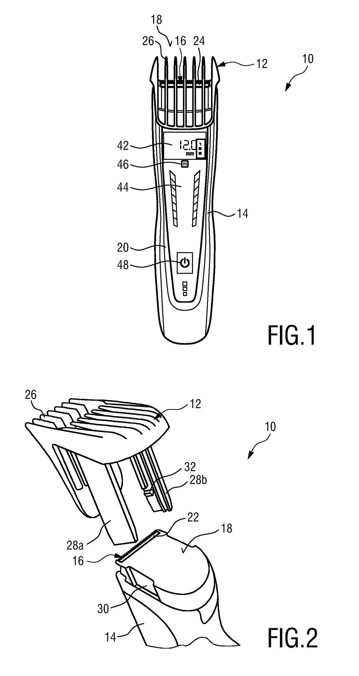
[0053]FIGS. 1 and 2 show an exemplary embodiment of the hair clipping device according to the present invention in a top view (FIG. 1) as well as in a partial exploded view (FIG. 2). The hair clipping device is therein in its entirety denoted with reference numeral 10.

[0054]The hair clipping device 10 comprises a comb attachment 12 which is releasably attachable to the hair clipping device 10. The hair clipping device 10 further comprises a housing 14 in which all remaining parts are usually integrated and to which the comb attachment 12 may be attached. The housing 14 also serves as a holder for a cutting assembly 16. The cutting assembly 16 may be releasably fixed to a distal end 18 of the housing 14. The cutting assembly 16 may, however, also be permanently fixed to the distal end 18 of the housing. The housing 14 is usually realized as an elongated body that forms a handle 20 at its rear end, i.e. the end opposite the distal end 18.

[0055]The cutting assembly 16 comprises a stati...


PUM


Abstract

The present invention relates to a hair clipping device (10) comprising: a housing (14), a cutting assembly (16) for clipping hairs, a comb attachment (12) which is attachable to the housing (14), a drive unit (38) for moving the comb attachment (12) relative to the cutting assembly (16) between different comb positions in order to set a hair cut-length, a control unit (36) for controlling the drive unit (38), a memory unit (40), and a user interface (34). The user interface (34) is configured to receive from a user a first memory input indicative of a first comb position and to send a first memory signal to the control unit (36) in response to receiving the first memory input, and wherein the user interface (34) is configured to receive from the user a first recall input indicative of the first comb position and to send a first recall signal to the control unit (36) in response to receiving the first recall input, wherein the control unit (36) is configured to store position information regarding the first comb position in the memory unit (40) in response to receiving the first memory signal, and wherein the control unit (36) is configured to recall the position information regarding the first comb position from the memory unit (40) in response to receiving the first recall signal and to control the drive unit (38) to move the comb attachment (12) to the first comb position according to the position information regarding the first comb position.

Description

FIELD OF THE INVENTION[0001]The present invention relates to a hair clipping device with a comb attachment that is attachable to the housing of the hair clipping device. The present invention particularly relates to a hair clipping device with a memory function allowing users to store their favorite length setting and quickly change the length setting by selecting a memory entry.BACKGROUND OF THE INVENTION[0002]Electric hair cutting appliances are generally known and include trimmers, clippers and shavers, whether powered by main supplied electricity or batteries. Such devices are generally used to trim body hair, in particular facial and head hair to allow a person to have a well-groomed appearance.[0003]Commonly, conventional devices for cutting hair comprise a main body forming an elongate housing having a front or cutting end (herein referred to as distal end) and an opposing handle end. A cutting assembly is disposed at the distal end. The cutting assembly usually comprises a s...

Claims


Application Information

Patent Timeline
IPC IPC(8): B26B19/38B26B19/06B26B19/20
CPCB26B19/388B26B19/06B26B19/20
Inventor VONK, ARJAN SANDERLATUL, JULIEN PHILIPPE
Owner KONINKLJIJKE PHILIPS NV
Learn More