
Process and installation for producing a composite material part

Active Publication Date: 2017-05-11
AIRBUS SAS
View PDF2 Cites 1 Cited by
  • Summary
  • Abstract
  • Description
  • Claims
  • Application Information

AI Technical Summary

Benefits of technology

The present invention provides a process for producing composite parts that are cost-effective and fast. By using different orientations of fibers, the distribution of heat is better, resulting in more efficient production. The pressing means used during polymerization expel air and solvents, reducing porosity and improving the quality of the composite material. Overall, this process allows for the production of high-quality composite parts with improved energy efficiency.

Problems solved by technology

However, it is observed that a high amount of energy is necessary to heat the tools, often made of metal, and the volume of the oven or autoclave used, having serious financial repercussions from the point of view of energy consumption.
Moreover, by virtue of the high quantities of energy required and the high thermal inertia of the means used, heating speeds are often limited to less than 1° C. / minute.
Now, since production rates are becoming faster, the means traditionally used will quickly be limited, except for multiplying in number and consequently substantially increasing the manufacturing costs, which is contradictory to the economic interests of manufacturing companies.

Method used


Image

  • Process and installation for producing a composite material part
  • Process and installation for producing a composite material part

Examples


Embodiment Construction

[0059]First of all, it is noted that the drawings are not to scale.

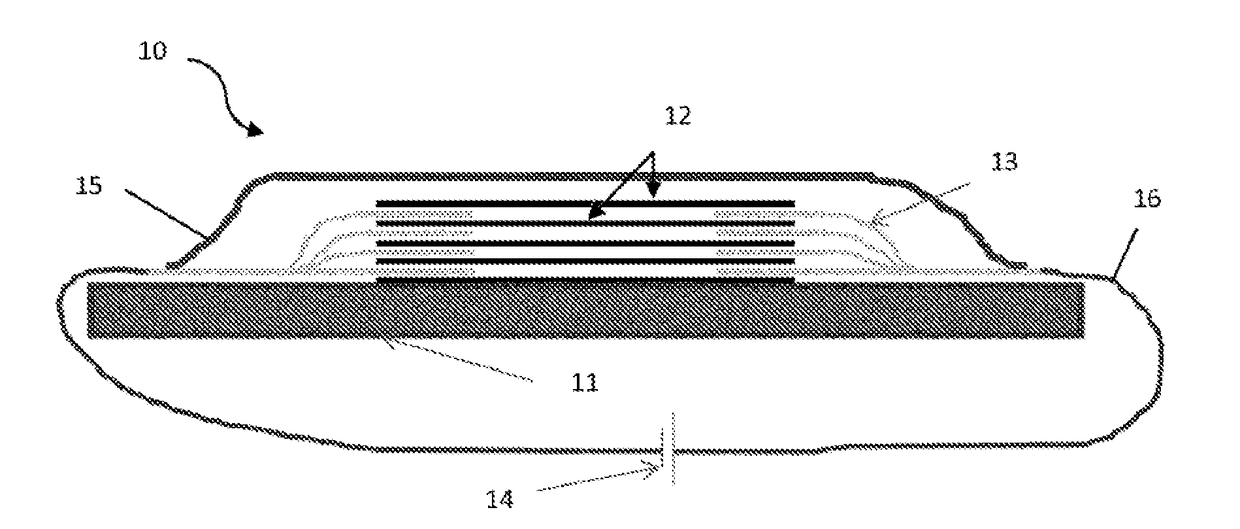
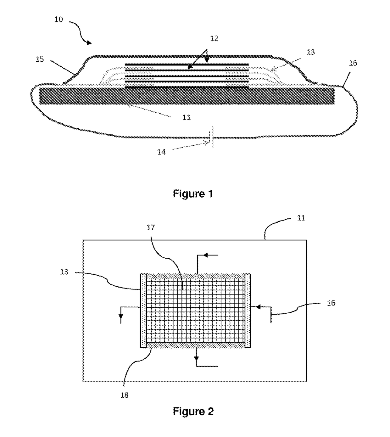
[0060]FIG. 1 schematically represents a cross-sectional view and a face view of an installation 10 for producing a composite material part according to a particular aspect of the presently disclosed embodiment.

[0061]This part is produced here by stacking on a flat-shaped half-mold 11 plies 12 of fibers pre-impregnated with resin. Of course, this tool 11 could exhibit a shape that is not flat, such as a convex shape, depending on the final shape to be conferred to said part. This half-mold 11 is in this case produced from an electrically insulating material such as a glass-fiber-based composite material.

[0062]Each ply 12 is in this case formed by unidirectional fibers that are continuous and electrically conducting, such as carbon fibers, these plies being deposited for example using a drape-forming machine (not represented).

[0063]Placed between two successive plies 12 of the stack thus produced are two metal foils 13...


PUM

PropertyMeasurementUnit
Temperatureaaaaaaaaaa
Pressureaaaaaaaaaa
Electrical conductivityaaaaaaaaaa

Abstract

A process and installation for producing a composite material part in which plies of continuous and electrically conductive fibres are deposited to form a stack of piles on a substrate. At least the face of the substrate bearing the stack is electrically insulating and the following steps are carried out a) an electrical terminal is inserted between the ends of at least two plies placed directly one on top of the other in the stack, and on at least two opposite sides of these plies b) when the fibres are dry, introducing a resin in order to impregnate the fibres and c) making a current flow between the electrical terminals through the plies in order to set the resin by resistive heating.

Description

CROSS-REFERENCE TO RELATED APPLICATIONS[0001]This application is the National Stage of International Application No. PCT / EP2015 / 0573G9, having an International Filing Date of 2 Apr. 2015, which designated the United States of America, and which International Application was published under PCT Article 21(2) as WO Publication No. 2015 / 150515 A1, and which claims priority from, and the benefit of, French Application No. 1452946, filed on 3 Apr. 2014, the disclosures of which are incorporated herein by reference in their entireties.BACKGROUND[0002]1. Field[0003]The presently disclosed embodiment relates to a process for producing parts made of composite materials with fibrous reinforcements.[0004]It furthermore relates to an installation for implementing this method.[0005]2. Brief Description of Related Developments[0006]The technical advantages of composite materials have resulted in a growth in their distribution in the most wide-ranging technological fields, and they are becoming in...

Claims


Application Information

Patent Timeline
IPC IPC(8): B29C70/44B29C70/54B29C35/02
CPCB29C70/443B29C35/0272B29C35/0288B29K2105/0845B29C2035/0211B29L2009/00B29C70/54B29C70/40B29C2033/023
Inventor CINQUIN, JACQUES
Owner AIRBUS SAS
Learn More