
Blade levelling apparatus and mounting system

Active Publication Date: 2017-05-11
PROGRESSIVE IP
View PDF1 Cites 1 Cited by
  • Summary
  • Abstract
  • Description
  • Claims
  • Application Information

AI Technical Summary

Benefits of technology

The present invention provides a blade levelling assembly that allows the blade to move vertically and rotate around a perpendicular axis. Its unique design uses linear actuators and stabilizing linkages to ensure the blade remains at the same angle regardless of its vertical position or rotational movement. The assembly is reliable and effective in balancing and leveling blades.

Problems solved by technology

Achieving this requires operator skill, and patience.
This makes levelling mounds and slopes to the true horizontal extremely difficult.
These rotational arrangements are expensive, and also add considerable weight to the load carried by the tractor unit.
They are also limited in the degree of precision with respect to inclination to a particular angle, and relatively slow to adjust.
This slows any levelling operation.
Attempting to use a standard tilt adjustable hitch as well as the levelling assembly tends to add too much weight to the end of the excavator arm, and limits its usefulness—especially on smaller excavators able to operate in tight confines.
Hence the use of blades on excavators, while desirable and useful, has been hindered and limited.

Method used


Image

  • Blade levelling apparatus and mounting system
  • Blade levelling apparatus and mounting system
  • Blade levelling apparatus and mounting system

Examples


Embodiment Construction

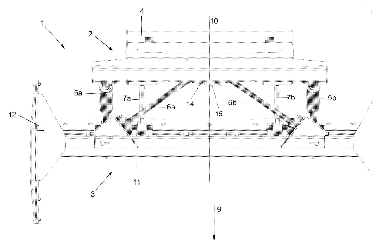
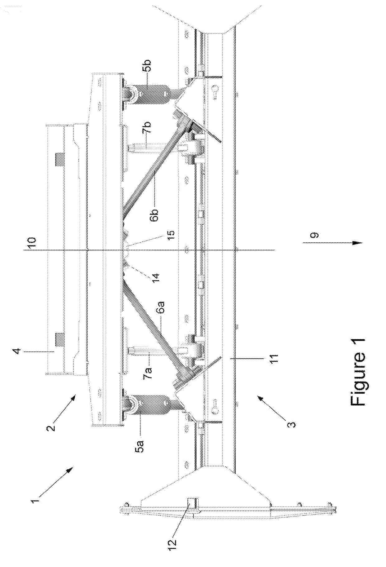
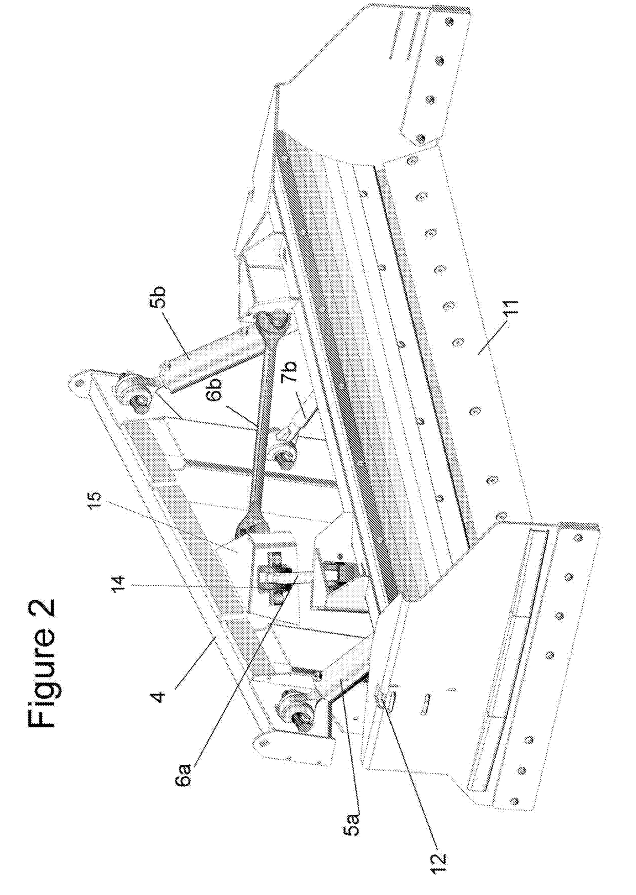
[0072]With reference to the drawings, and by way of example only, there is provided a levelling assembly (generally indicated by arrow 1) comprising a body attachment portion (generally indicated by arrow 2) and a blade body portion (generally indicated by arrow 3);

[0073]the two body portions (2, 3) being connected by body connecting linkages (5-7) which allow a substantially translational movement of the blade body portion (3), substantially parallel and relative to the blade body portion (2)—see for instance FIGS. 3a and 3b; the body connecting linkages (5-7) also allowing a rotational movement of the blade body portion (3), relative to the body attachment portion (2), about a rotational axis substantially in the direction of forward travel (9) of the assembly (1)—see for instance FIG. 3c;

said body connecting linkages including linear actuators (5a, b), there being at least one linear actuator (5) being present either side of the middle (10) of the levelling assembly (1) when vie...


PUM


Abstract

The present invention is directed to levelling apparatus, typically as used on tractors, excavators and skid-steer vehicles, and references the levelling assembly and mounting options including directly to the existing blade of vehicles as well as other mounting arrangements. Preferred embodiments of a levelling apparatus include a blade body portion and body mounting portion connected by an arrangement of fixed and adjustable linkages, preferably hydraulic, to allow movement of the blade body portion (relative to the body mounting portion) in substantially an up and down direction, as well as rotational movement about an axis perpendicular to the general plane of an attached blade.

Description

FIELD OF INVENTION[0001]The present invention is directed to levelling apparatus, typically as used on tractors and skid-steer vehicles. The present invention has the ability to vary the inclination of the blade portion, about an axis substantially parallel to the direction of travel during use, as well as normal elevation functions.BACKGROUND DESCRIPTION[0002]The present invention relates to levelers, a device typically attached to tractors, excavators, and skid-steer vehicles for the purpose of levelling and smoothing the ground. It is envisaged however that the present invention may find other uses, and be adapted therefore.[0003]Levelers take many shapes and designs, including those which are merely dragged along the ground. Many, however, have blades (sometimes known as mould boards) for levelling and altering the contour of the ground. In these versions, the height of the blade is typically able to be altered, which allows the user control over grading, levelling and / or sculpt...

Claims


Application Information

Patent Timeline
IPC IPC(8): E02F3/815E02F3/76E02F3/96E02F3/84
CPCE02F3/815E02F3/844E02F3/963E02F3/961E02F3/7631E02F3/7672E02F3/7677E02F3/847E02F3/962
Inventor SHARP, RODNEY WARWICK
Owner PROGRESSIVE IP
Learn More