Method for locating an object using an fmcw radar

a technology of locating objects and radars, applied in the direction of reradiation, measurement devices, instruments, etc., can solve the problems of significant cost saving, and achieve the effect of suppressing the disturbing influence of noise and clutter

Active Publication Date: 2017-05-11
ROBERT BOSCH GMBH
View PDF19 Cites 12 Cited by
  • Summary
  • Abstract
  • Description
  • Claims
  • Application Information

AI Technical Summary

Benefits of technology

[0016]The object of the present invention is therefore to indicate a method that makes it possible to further suppress the disturbing influences of noise and clutter.

Problems solved by technology

This results in a significant saving of costs.

Method used


Image

  • Method for locating an object using an fmcw radar
  • Method for locating an object using an fmcw radar
  • Method for locating an object using an fmcw radar

Examples


Embodiment Construction

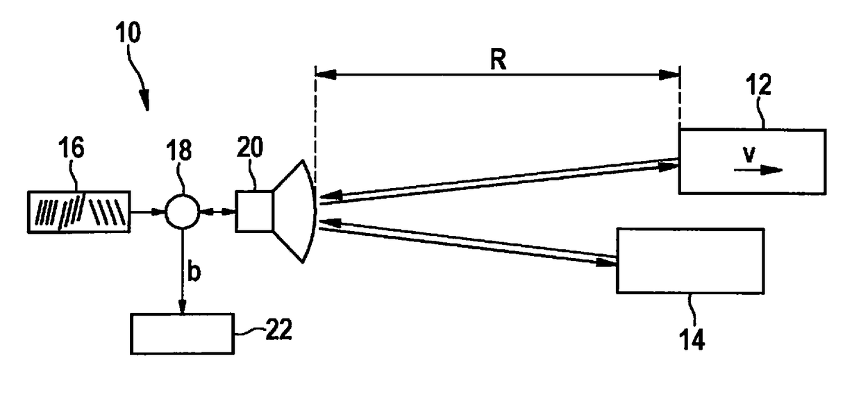
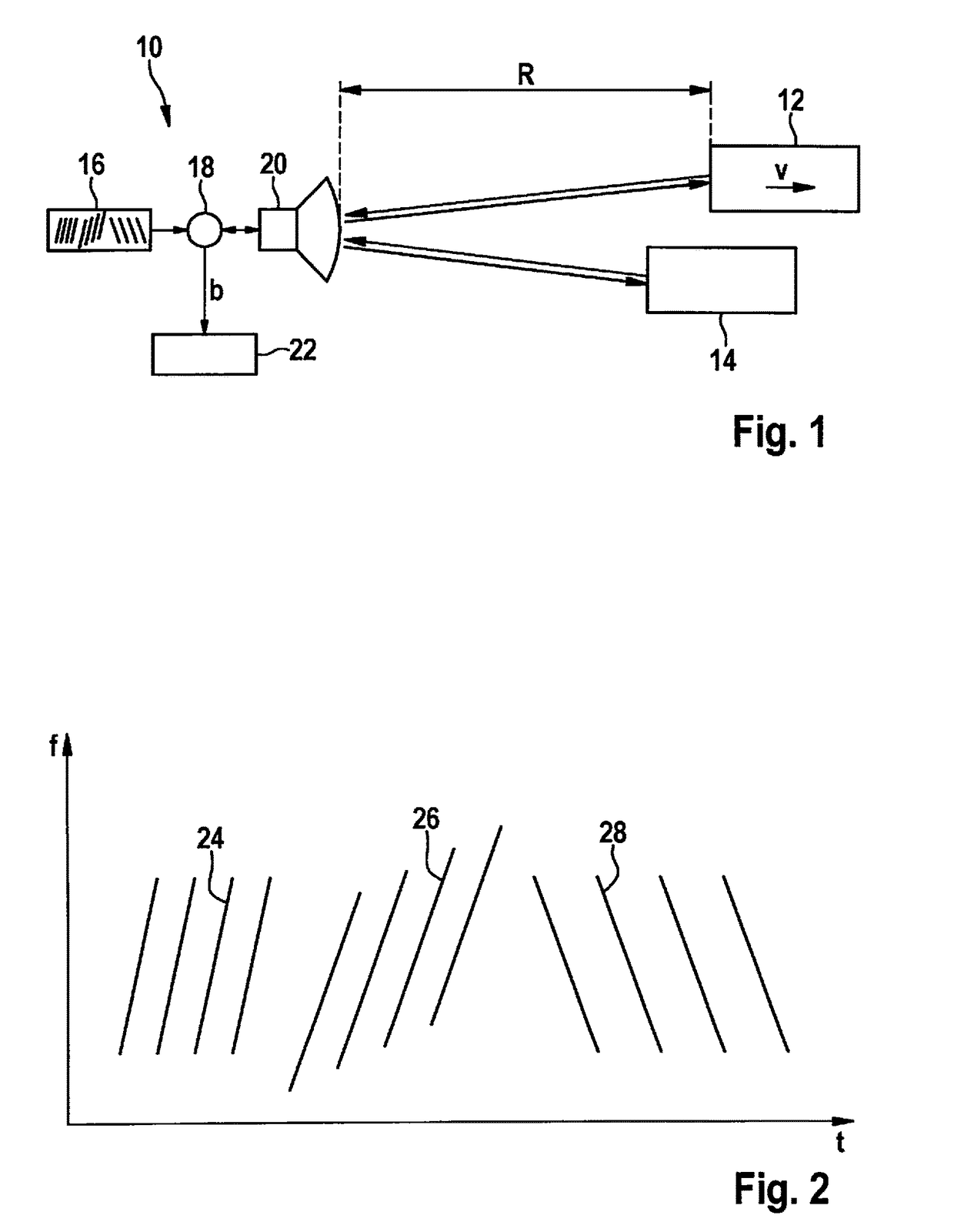
[0040]FIG. 1 shows, as a simplified block diagram, an FMCW radar sensor 10 that is for example installed at the front in a motor vehicle, and is used to measure distances R and relative velocities v of objects 12, 14, for example vehicles traveling in front. Radar sensor 10 has a voltage-controlled oscillator 16 that, via a mixer 18, supplies a frequency-modulated transmit signal to a transceiver device 20, by which the signal is sent out in the direction towards objects 12, 14. The signal reflected by the objects is received by transceiver device 20 and is mixed with a portion of the transmit signal in mixer 18. In this way, a baseband signal b is obtained that is further evaluated in an electronic evaluation and control device 22.

[0041]FIG. 2 shows an example of a modulation schema of the transmit signal provided by oscillator 16. Frequency f of the transmit signal is here plotted as a function of time t. The frequency is modulated in the form of successive ramps 24, 26, 28. In th...


PUM


Abstract

A method for locating objects using an FMCW radar in which a ramp-shaped frequency-modulated radar signal is transmitted whose modulation pattern has a plurality of successive ramps having different gradients, received radar echoes are mixed down with the transmitted signal into a baseband, the baseband signal is recorded ramp-by-ramp and transformed into a respective spectrum, for each signal peak found in the spectrum, a noise estimation is carried out in order to distinguish between radar targets and noise or clutter, and by comparing the frequency positions of the mutually corresponding signal peaks in the spectra obtained for various ramp gradients, the distances and relative velocities of the radar targets are determined.

Description

BACKGROUND INFORMATION[0001]The present invention relates to a method for locating objects using an FMCW radar, in which:[0002]a ramp-shaped frequency-modulated radar signal is transmitted whose modulation pattern has a plurality of successive ramps having different gradients,[0003]received radar echoes are mixed down with the transmitted signal into a baseband,[0004]the baseband signal is recorded ramp-by-ramp and transformed into a respective spectrum,[0005]for each signal peak found in the spectrum, a noise estimation is carried out in order to distinguish between radar targets and noise or clutter, and[0006]by comparing the frequency positions of the mutually corresponding signal peaks in the spectra obtained for various ramp gradients, the distances R and relative velocities v of the radar targets are determined.[0007]In addition, the present invention relates to a radar sensor, in particular for motor vehicles, fashioned in order to carry out this method.[0008]In motor vehicle...

Claims


Application Information

Patent Timeline
Patent Type & Authority Applications(United States)
IPC IPC(8): G01S13/58G01S7/35G01S7/41G01S13/02G01S13/931
CPCG01S13/584G01S7/414G01S7/354G01S13/0209G01S13/34G01S13/931G01S13/536G01S2013/932G01S7/356
Inventor SCHOOR, MICHAEL
Owner ROBERT BOSCH GMBH
Why Eureka
Try Eureka