Optical Ring Modulator Thermal Tuning Technique

a technology of optical ring modulator and thermal tuning, which is applied in the direction of optical waveguide light guide, optical light guide, instruments, etc., can solve the problems of thermal fluctuations of conventional optical ring modulators, large drive voltage, and relatively high power consumption of mach-zehnder based opto-electronic modulators

Active Publication Date: 2017-05-11
CALIFORNIA INST OF TECH
View PDF1 Cites 4 Cited by
  • Summary
  • Abstract
  • Description
  • Claims
  • Application Information

AI Technical Summary

Problems solved by technology

As is known, Mach-Zehnder based opto-electronic modulators have a relatively high power consumption, are large and require a high drive voltage.
Conventional optical ring modulators are susceptible to thermal fluctuations.
Thermal fluctuations of an optical ring modulator may be caused by ambient thermal noise as well as data-dependent self-heating of the device.
Therefore, reducing the heat capacity exacerbates data-dependent self-heating.
Data-dependent self-heating requires relatively fast thermal tuning which is difficult to achieve with resistive heaters.

Method used


Image

  • Optical Ring Modulator Thermal Tuning Technique
  • Optical Ring Modulator Thermal Tuning Technique
  • Optical Ring Modulator Thermal Tuning Technique

Examples


Embodiment Construction

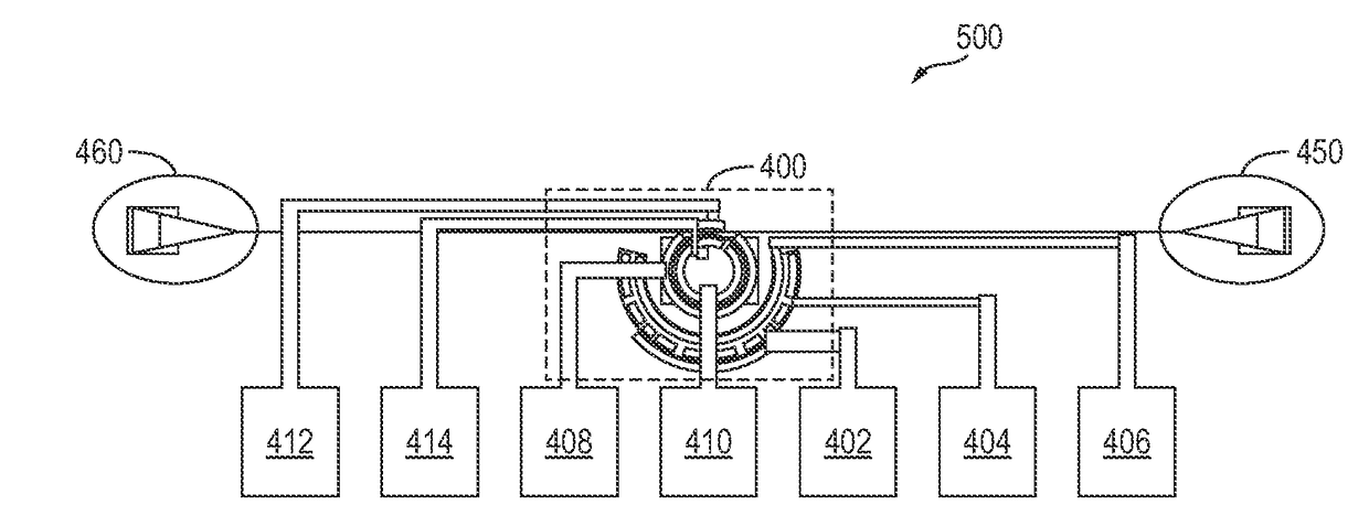
[0031]In accordance with embodiments of the present invention, the temperature of an optical modulator is controlled via a feedback or feedforward loop that senses the temperature of the optical modulator.

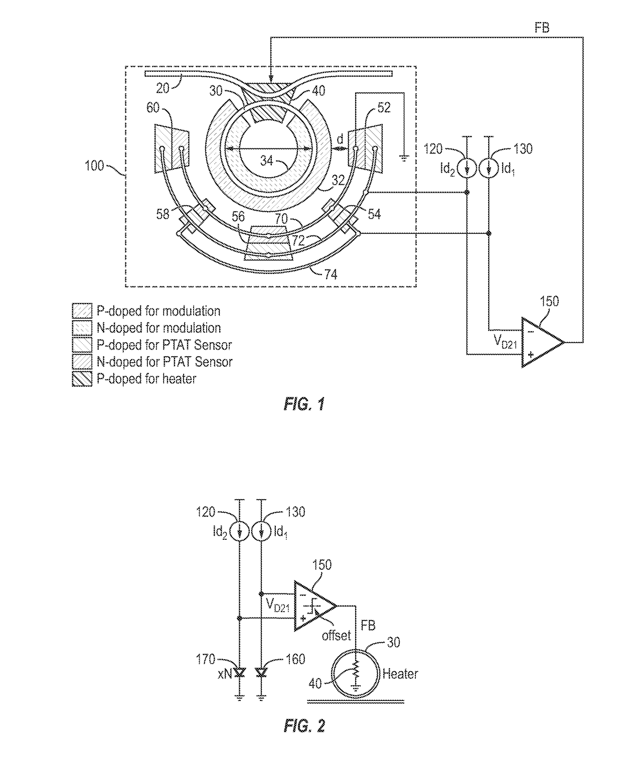
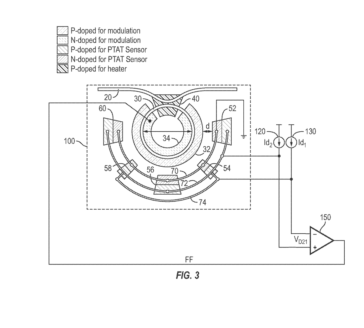
[0032]FIG. 1 is a simplified schematic top layout view of an integrated optical modulator 100, in accordance with one exemplary embodiment of the present invention. Integrated optical modulator 100 is shown as including, in part, a waveguide 20, and an optical ring 30. The optical signal traveling through waveguide 20 is coupled to optical ring 30.

[0033]Exemplary integrated optical ring modulator (hereinafter alternatively referred to as modulator) 30 is shown as further including, in part, p-doped region 32 and n-doped region 34 positioned along the inner periphery and outer periphery of ring 30 respectively. Modulator 30 is also shown as including a p-doped region 40 formed below the area where waveguide 20 is bent to enable the coupling of the light between waveguide 20 and ring...


PUM

PropertyMeasurementUnit
distanceaaaaaaaaaa
full-width half-maximumaaaaaaaaaa
saturation currentsaaaaaaaaaa

Abstract

An optical signal modulator (modulator) includes, in part, a first multitude of diodes coupled in parallel and disposed along an outer periphery of the optical ring of the modulator, a second multitude of diodes coupled in parallel and disposed along the outer periphery of the optical ring, and a doped region adapted to supply heat to the optical ring. A pair of current sources supply substantially constant currents to the first and second multitude of diodes to generate a pair of electrical signals. The modulator further includes, in part, a control circuit adapted to control the temperature of the optical ring in accordance with the pair electrical signals. To achieve this, the control circuit varies the voltage applied to the doped region to vary the supplied heat. Alternatively, the control circuit applies a voltage to the optical ring to maintain a substantially constant resonant wavelength in the optical ring.

Description

CROSS REFERENCE TO RELATED APPLICATIONS[0001]The present application claims benefit under 35 USC 119 (e) of U.S. provisional Application No. 62 / 165,410, filed May 22, 2015, entitled “Optical Ring Modulator Thermal Tuning Technique”, the content of which is incorporated herein by reference in its entirety.FIELD OF THE INVENTION[0002]The present invention relates to optoelectronic devices, and more particularly to optical ring modulators.BACKGROUND OF THE INVENTION[0003]Electro-optic modulators (EOM) are commonly used in optical communication networks. A phase-modulating EOM may be used in a Mach-Zehnder interferometer to modulate the amplitude of an incoming optical signal. As is known, Mach-Zehnder based opto-electronic modulators have a relatively high power consumption, are large and require a high drive voltage.[0004]Improving the bandwidth-density product in an integrated silicon photonic system requires a corresponding improvement in the performance of the optical modulator dis...

Claims


Application Information

Patent Timeline
Patent Type & Authority Applications(United States)
IPC IPC(8): G02F1/225G02B6/122
CPCG02F1/2257G02B6/122G02B2006/12159G02F2201/06G02F2001/212G02B6/12007G02F1/0121G02F1/0147G02F1/025G02F2201/58G02F2203/15G02B6/00G02B6/12G02B6/293G02F1/212
Inventor SAEEDI, SAMANEMAMI, AZITA
Owner CALIFORNIA INST OF TECH
Why Eureka
Try Eureka