Optical sensor module utilizing optical designs to adjust gesture sensitive region, and related mobile apparatus

a technology of optical design and optical sensor, applied in the field of optical sensors, can solve problems such as inconvenience for users, and achieve the effect of intuitive and convenient control

Inactive Publication Date: 2017-05-11
EMINENT ELECTRONICS TECH
View PDF3 Cites 1 Cited by
  • Summary
  • Abstract
  • Description
  • Claims
  • Application Information

AI Technical Summary

Benefits of technology

[0014]The proposed optical sensor module may be employed in various electronic products (e.g. a portable apparatus such as a mobile phone or a tablet computer), and utilize optical path designs to adjust a non-contact gesture sensitive region, thus allowing intuitive and convenient control.

Problems solved by technology

However, when the user performs the non-contact gesture (e.g. the hand moves rightward or leftward), the user's elbow blocks the user's view of the display screen 104, which causes inconvenience to the user.

Method used


Image

  • Optical sensor module utilizing optical designs to adjust gesture sensitive region, and related mobile apparatus
  • Optical sensor module utilizing optical designs to adjust gesture sensitive region, and related mobile apparatus
  • Optical sensor module utilizing optical designs to adjust gesture sensitive region, and related mobile apparatus

Examples


Embodiment Construction

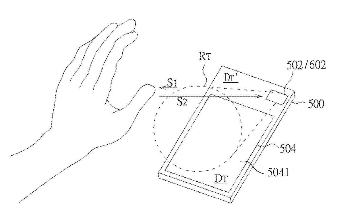
[0043]By means of optical path designs (e.g. changing a light receiving range of a sensor in space, and / or changing an illumination range of a light source in space), the proposed light sensing architecture may realize a non-contact gesture sensitive region (or a non-contact working range) which meets user's habits. To facilitating an understanding of the present invention, an exemplary implementation of an electronic apparatus (or an optical sensor module), which recognizes a non-contact gesture according to a phase difference between reflected signals, is given in the following for further description of the proposed light sensing architecture. However, the proposed light sensing architecture may be employed in an electronic apparatus (or an optical sensor module) which utilizes other detection mechanisms (e.g. detecting an object image or calculating an object position) to recognize a non-contact gesture.

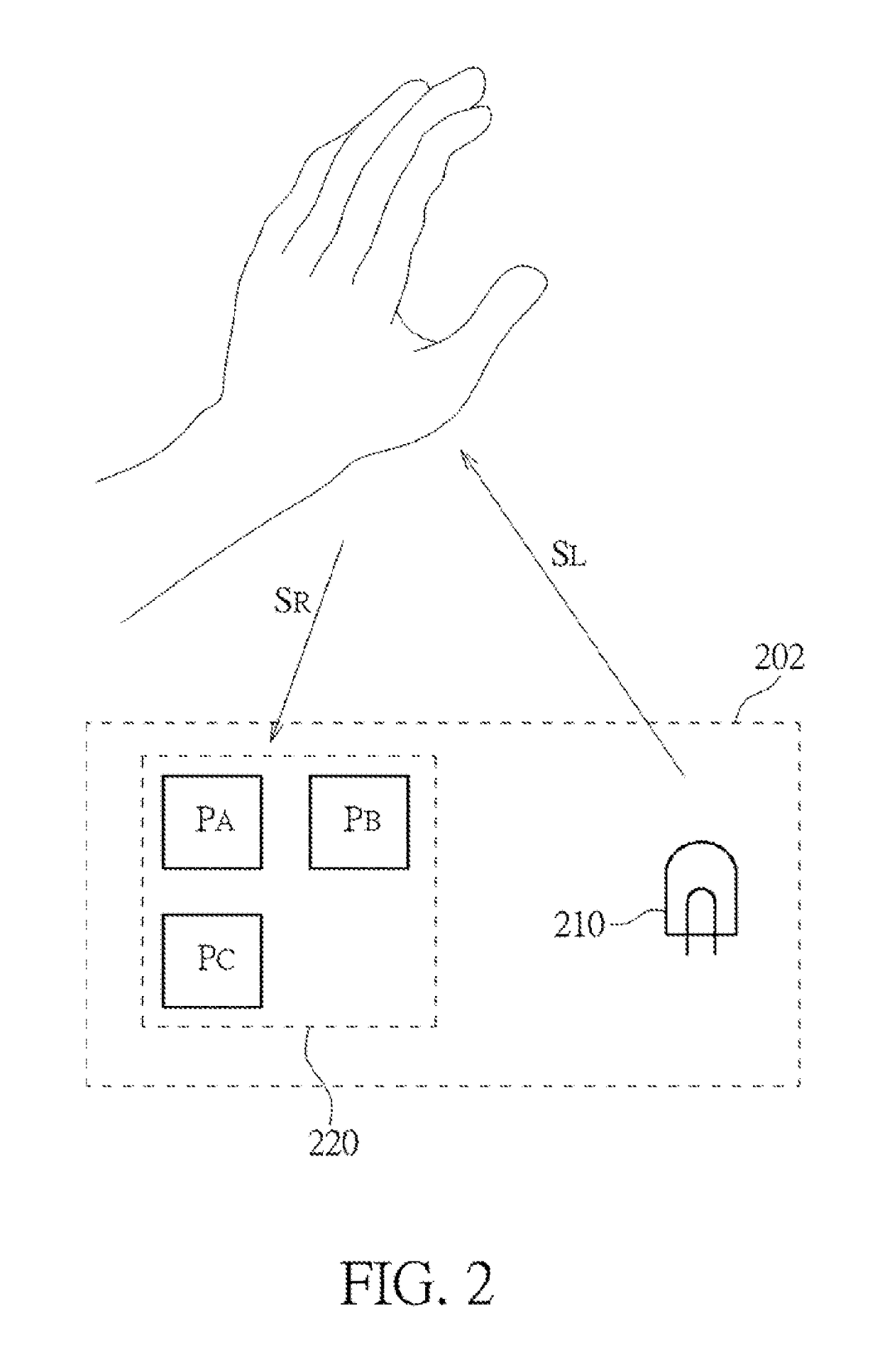
[0044]FIG. 2 is a diagram illustrating an exemplary optical sensor module ac...


PUM


Abstract

An optical sensor module is provided. The optical sensor module includes a light source, a first lens and a sensor device. The light source is arranged for generating a light signal. The first lens has a first optical center axis. The sensor device is disposed in correspondence with one side of the first lens. The sensor device includes a light sensitive area, and a center of the light sensitive area deviates from the first optical center axis. The sensor device is arranged for receiving a reflected signal reflected from an object in response to the light signal, and accordingly generating a sensing result.

Description

CROSS-REFERENCE TO RELATED APPLICATIONS[0001]This application is a continuation-in-part application of U.S. patent application filed on May 7, 2015 and having application Ser. No. 14 / 705,995, the entire contents of which are hereby incorporated herein by reference.[0002]This application claims the benefit of U.S. provisional application filed on May 9, 2014 and having application Ser. No. 61 / 990,718, the entire contents of which are hereby incorporated herein by reference.[0003]This application is based upon and claims priority under 35 U.S.C. 119 from Taiwan Patent Application No. 104111320 filed on Apr. 8, 2015, which is hereby specifically incorporated herein by this reference thereto.BACKGROUND OF THE INVENTION[0004]1. Field of the Invention[0005]The disclosed embodiments of the present invention relate to an optical sensor, and more particularly, to an optical sensor module utilizing optical designs to change a non-contact gesture sensitive region, and a related mobile apparatu...

Claims


Application Information

Patent Timeline
Patent Type & Authority Applications(United States)
IPC IPC(8): G06F3/03G02B3/04G06F3/01
CPCG06F3/0304G02B3/04G06F3/017G06F3/011
Inventor SUNG, HSIN-YUEHCHEN, YI-YUNGCHANG, TOMWU, KAO-PINCHUANG, CHENG-TAHSU, WEI-TE
Owner EMINENT ELECTRONICS TECH
Why Eureka
Try Eureka