
Harmonicity-dependent controlling of a harmonic filter tool

Active Publication Date: 2017-05-11
FRAUNHOFER GESELLSCHAFT ZUR FOERDERUNG DER ANGEWANDTEN FORSCHUNG EV
View PDF3 Cites 36 Cited by
  • Summary
  • Abstract
  • Description
  • Claims
  • Application Information

AI Technical Summary

Benefits of technology

The patent text explains a way to improve the efficiency of an audio codec by using a harmonic filter tool that can be controlled based on the pitch of the audio signal. This results in a situation-adapted control of the harmonic filter tool, which can improve coding efficiency in certain situations while avoiding unnecessary processing in others.

Problems solved by technology

Transform-based audio codecs like AAC, MP3, or TCX generally introduce inter-harmonic quantization noise when processing harmonic audio signals, particularly at low bitrates.
This effect is further worsened when the transform-based audio codec operates at low delay, due to the worse frequency resolution and / or selectivity introduced by a shorter transform size and / or a worse window frequency response.
This inter-harmonic noise is generally perceived as a very annoying “warbling” artifact, which significantly reduces the performance of the transform-based audio codec when subjectively evaluated on highly tonal audio material like some music or voiced speech.
However, using such techniques in signals with changing temporal structure again leads to unwanted effects such as temporal smearing of percussive musical events or speech plosives or even the creation of impulse trails due to the repetition of a single impulse-like transient.
The reason for this design seems to stem from the general belief that, in a mix of harmonic and transient signal components, the transient dominates the mix, and activating LTP or pitch prediction upon it would, as discussed earlier, subjectively cause more harm than improvement.

Method used


Image

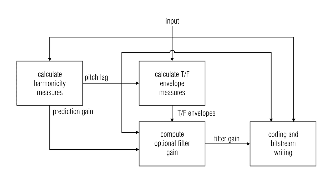
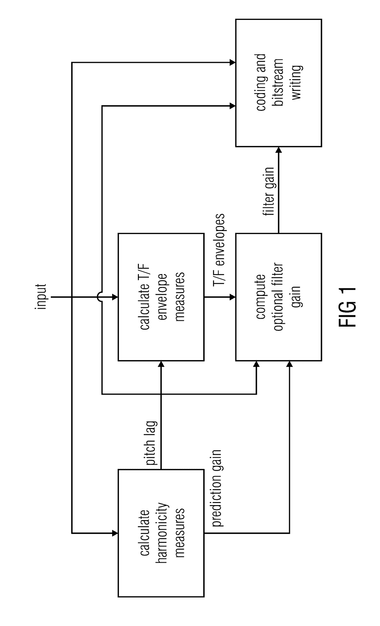
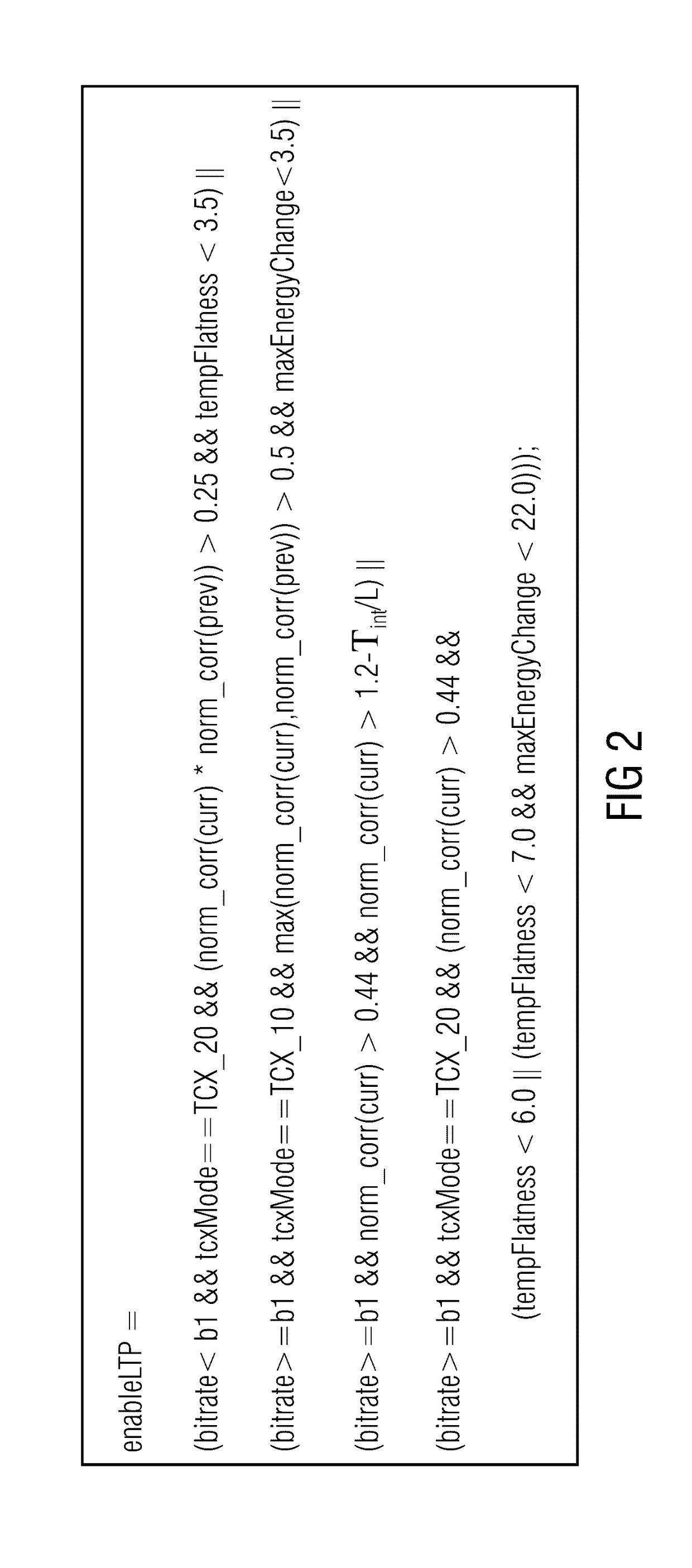
  • Harmonicity-dependent controlling of a harmonic filter tool
  • Harmonicity-dependent controlling of a harmonic filter tool
  • Harmonicity-dependent controlling of a harmonic filter tool

Examples


example 1

[0151]The size of the region in which temporal measures for the LTP decision are calculated is dependent on the pitch (see equation (8)) and this region is different from the region where temporal measures for the transform length are calculated (usually current frame plus look-ahead).

[0152]In the example in FIG. 11 the transient is inside the region where the temporal measures are calculated and thus influences the LTP decision. The motivation, as stated above, is that a LTP for the current frame, utilizing past samples from the segment denoted by “pitch lag”, would reach into a portion of the transient.

[0153]In the example in FIG. 12 the transient is outside the region where the temporal measures are calculated and thus doesn't influence the LTP decision. This is reasonable since, unlike in the previous figure, a LTP for the current frame would not reach into the transient.

[0154]In both examples (FIG. 11 and FIG. 12) the transform length configuration is decided on temporal measur...

example 2

[0155]Here we discuss the behavior of the LTP for impulse and step transients within harmonic signal, of which one example is given by signal's spectrogram in FIG. 13.

[0156]When coding the signal includes the LTP for the complete signal (because the LTP decision is based only on the pitch gain), the spectrogram of the output looks as presented in FIG. 14.

[0157]The waveform of the signal, which spectrogram is in FIG. 14, is presented in FIG. 15. The FIG. 15 also includes the same signal Low-pass (LP) filtered and High-pass (HP) filtered. In the LP filtered signal the harmonic structure becomes clearer and in the HP filtered signal the location of the impulse like transient and its trail is more evident. The level of the complete signal, LP signal and HP signal is modified in the figure for the sake of the presentation.

[0158]For short impulse like transients (as the first transient in FIG. 13), the long term prediction produces repetitions of the transient as can be seen in FIG. 14 an...

example 3

[0160]However in some cases the usage of the temporal measures may be disadvantageous. The spectrogram in FIG. 18 and the waveform in FIG. 19 display an excerpt of about 35 milliseconds from the beginning of “Kalifornia” by Fatboy Slim.

[0161]The LTP decision that is dependent on the Temporal Flatness Measure and on the Maximum Energy Change disables the LTP for this type of signal as it detects huge temporal fluctuations of energy.

[0162]This sample is an example of ambiguity between transients and train of pulses that form low pitched signal.

[0163]As can be seen in FIG. 20, where the 600 milliseconds excerpt from the same signal the signal is presented, the signal contains repeated very short impulse like transient (the spectrogram is produced using short length FFT).

[0164]As can be seen in the same 600 milliseconds excerpt in FIG. 21 the signal looks as if it contains very harmonic signal with low and changing pitch (the spectrogram is produced using long length FFT).

[0165]This kin...


PUM


Abstract

The coding efficiency of an audio codec using a controllable—switchable or even adjustable—harmonic filter tool is improved by performing the harmonicity-dependent controlling of this tool using a temporal structure measure in addition to a measure of harmonicity in order to control the harmonic filter tool. In particular, the temporal structure of the audio signal is evaluated in a manner which depends on the pitch. This enables to achieve a situation-adapted control of the harmonic filter tool so that in situations where a control made solely based on the measure of harmonicity would decide against or reduce the usage of this tool, although using the harmonic filter tool would, in that situation, increase the coding efficiency, the harmonic filter tool is applied, while in other situations where the harmonic filter tool may be inefficient or even destructive, the control reduces the appliance of the harmonic filter tool appropriately.

Description

CROSS-REFERENCE TO RELATED APPLICATION[0001]This application is a continuation of copending International Application No. PCT / EP2015 / 067160, filed Jul. 27, 2015, which claims priority from European Application No. EP 14178810.9, filed Jul. 28, 2014, which are each incorporated herein in its entirety by this reference thereto.[0002]The present application is concerned with the decision on controlling of a harmonic filter tool such as of the pre / post filter or post-filter only approach. Such tool is, for example, applicable to MPEG-D unified speech and audio coding (USAC) and the upcoming 3GPP EVS codec.BACKGROUND OF THE INVENTION[0003]Transform-based audio codecs like AAC, MP3, or TCX generally introduce inter-harmonic quantization noise when processing harmonic audio signals, particularly at low bitrates.[0004]This effect is further worsened when the transform-based audio codec operates at low delay, due to the worse frequency resolution and / or selectivity introduced by a shorter tr...

Claims


Application Information

Patent Timeline
IPC IPC(8): G10L19/26G10L25/21G10L19/12G10L19/025G10L19/22G10L25/90G10L19/028
CPCG10L19/265G10L25/90G10L25/21G10L19/12G10L19/025G10L19/22G10L19/028G10L19/26G10L19/125
Inventor MARKOVIC, GORANHELMRICH, CHRISTIANRAVELLI, EMMANUELJANDER, MANUELDOEHLA, STEFAN
Owner FRAUNHOFER GESELLSCHAFT ZUR FOERDERUNG DER ANGEWANDTEN FORSCHUNG EV
Learn More