Head-up display device and illumination unit for head-up display device
a display device and head-up technology, applied in the direction of lighting and heating equipment, instruments, lenses, etc., can solve the problems of physical size of the configuration may increase, difficult to reduce the focal length, and difficult to increase the curvature of the lens surface, so as to achieve high illumination efficiency, maintain the brightness of virtual images, and wide display area
- Summary
- Abstract
- Description
- Claims
- Application Information
AI Technical Summary
Benefits of technology
Problems solved by technology
Method used
Image
Examples
first embodiment
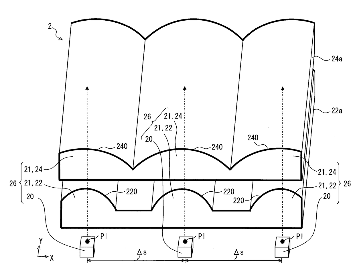
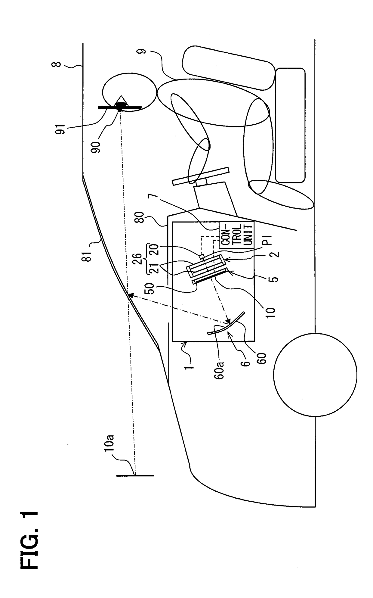
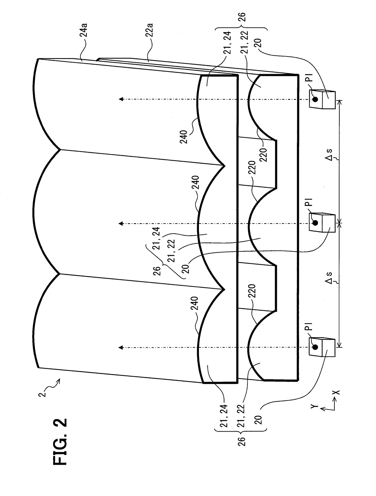
[0023]As shown in FIG. 1, a HUD device 1 according to a first embodiment of the present disclosure is mounted on a vehicle 8, which corresponds to a “moving body”, and is housed within an instrument panel 80. The HUD device 1 projects a display image 10 toward a windshield 81 of the vehicle 8. The windshield 81 corresponds to a “display member”. As a result, within the cabin of the vehicle 8, the light of the display image 10 is reflected at the windshield 81 and arrives at an eye point 90 of a viewer 9. The viewer 9 perceives the light arriving at the eye point 90, and as a result views a virtual image 10a of the display image 10 ahead of the windshield 81. The viewing of this virtual image 10a is confined to when the eye point 90 is positioned in a viewing area 91 inside the vehicle 8. In other words, if the eye point 90 is outside of the viewing area 91, it may be difficult for the viewer 9 to view the virtual image 10a.
[0024]The HUD device 1 includes an illumination unit 2, a d...
second embodiment
[0053]A second embodiment of the present disclosure, as shown in FIGS. 4 to 6, is a modified example of the first embodiment. In the second embodiment, among two stages of condenser lenses 2021 of each illumination module set 2026, a final stage lens 2024 is at a later stage than the initial stage lens 22. This final stage lens 2024 includes final stage lens surfaces 2242 formed of a plurality of alternatingly arranged first lens surface portions 2240 and second lens surface portions 2241.
[0054]As shown in FIG. 6, the first lens surface portion 2240 of each illumination module set 2026 is formed to have a shape such that, under an assumption that there are a plurality of first imaginary lens surfaces 2240a, portions are intermittently extracted from a respective corresponding first imaginary lens surface 2240a as shown by the dotted lines in this figure. Further, it is assumed there are three first imaginary lens surfaces 2240a, equal to the number of sets of illumination units 2026...
PUM
 Abstract
Description
Claims
Application Information
 - R&D
- Intellectual Property
- Life Sciences
- Materials
- Tech Scout
- Unparalleled Data Quality
- Higher Quality Content
- 60% Fewer Hallucinations
Browse by: Latest US Patents, China's latest patents, Technical Efficacy Thesaurus, Application Domain, Technology Topic, Popular Technical Reports.
© 2025 PatSnap. All rights reserved.Legal|Privacy policy|Modern Slavery Act Transparency Statement|Sitemap|About US| Contact US: help@patsnap.com


