
Touch display panel, producing method thereof, and display apparatus

a display panel and touch technology, applied in the field of display, can solve the problems of prone to touch mura, spot or bubbles, and the mura generated by too large touch force cannot be significantly suppressed, so as to avoid the effect of display mura and eliminate vibration sound waves

Active Publication Date: 2017-05-25
BOE TECH GRP CO LTD +1
View PDF0 Cites 5 Cited by
  • Summary
  • Abstract
  • Description
  • Claims
  • Application Information

AI Technical Summary

Benefits of technology

The present patent application provides a touch display panel with a sound elimination membrane that can reduce vibration sound waves during the knocking touch process. This helps to avoid display mura caused by vibration sound waves and improves the display effect. Overall, the touch display panel helps to enhance the display effect and suppress display mura during the knocking touch process.

Problems solved by technology

When a touch operation of the liquid crystal panel is performed, it tends to lead to touch mura.
At present, due to a relatively large stiffness, the protection cover glass (for example Corning Gorilla Glass) can effectively resist the first kind of touch mura caused by the deformation in the thickness direction of the liquid crystal cell, but the mura generated by too large touch force cannot be suppressed significantly.
However, this will bring about problems such as yellow spot or bubbles.

Method used


Image

  • Touch display panel, producing method thereof, and display apparatus
  • Touch display panel, producing method thereof, and display apparatus
  • Touch display panel, producing method thereof, and display apparatus

Examples


first embodiment

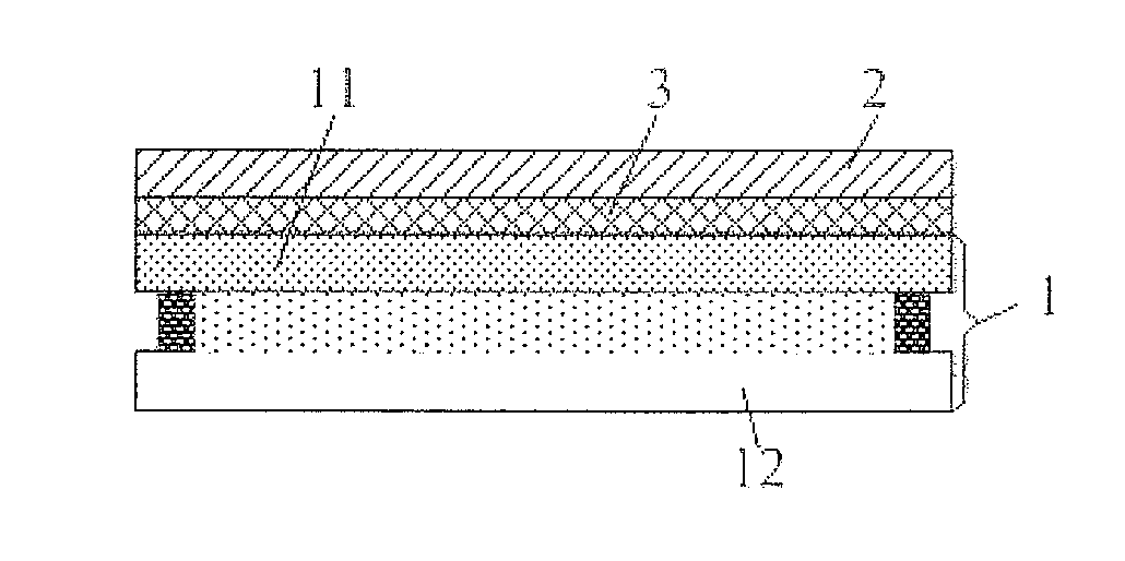
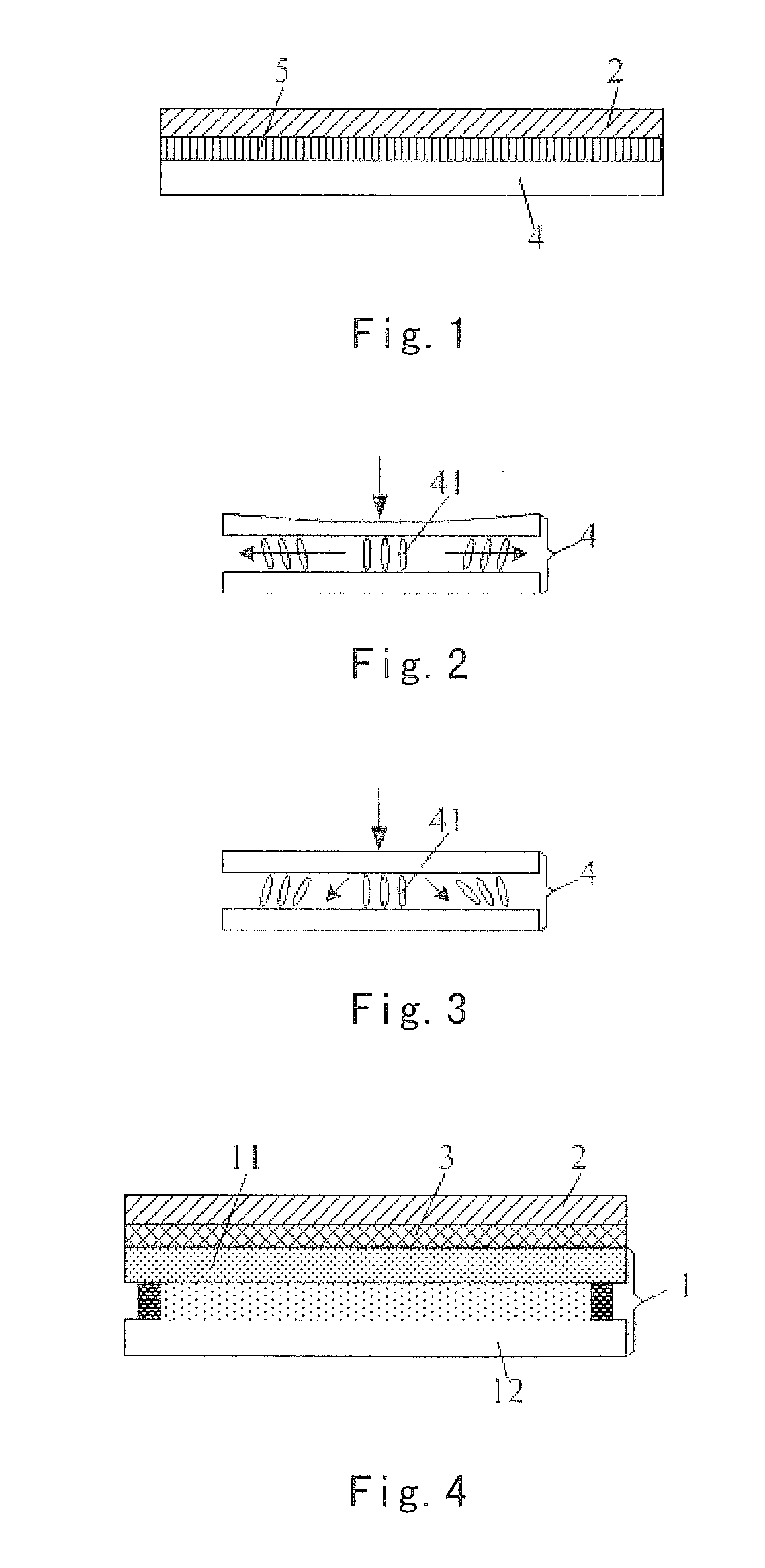
[0042]The present embodiment provides a touch display panel, as shown in FIG. 4, which includes a liquid crystal screen 1 and a protection cover plate 2 covered at a light exiting side of the liquid crystal screen 1. The touch display panel further includes a sound elimination membrane 3, located at the light exiting side of the liquid crystal screen 1. The sound elimination membrane 3 is used to eliminate the sound waves generated when touching the touch display panel.

[0043]In the present embodiment, the liquid crystal screen 1 includes a color filter substrate 11 and an array substrate 12 assembled together, and the color filter substrate 11 is located at a light exiting side of the liquid crystal screen 1. The protection cover plate 2 is located at one side of the color filter substrate 11 facing away from the array substrate 12, and the sound elimination membrane 3 is located between the color filter substrate 11 and the protection cover plate 2.

[0044]The sound elimination membr...

second embodiment

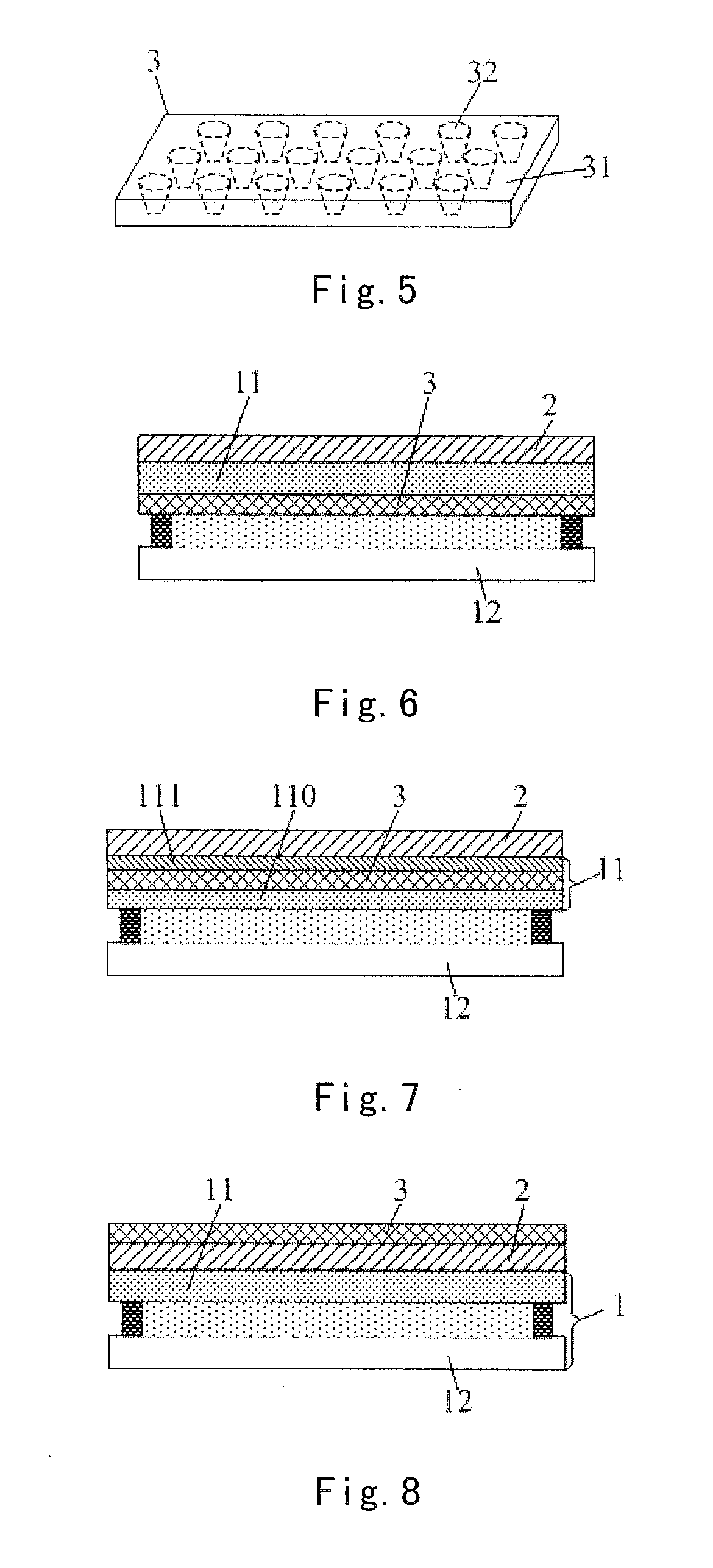
[0057]This embodiment provides a touch display panel. As shown in FIG. 6, the sound elimination membrane 3 is located at one side of the color filter substrate 11 facing away from the protection cover plate 2, which is different from that of the first embodiment.

[0058]In the present embodiment, the sound elimination membrane 3 is provided on the color filer substrate 11. With such arrangement, it can ensure the vibration sound waves generated by the knocking do not pass into the liquid crystal molecules, thereby avoiding the display mura of the touch display panel caused by the vibration sound waves.

[0059]Other structure arrangements of the touch display panel in the present embodiment and the producing method thereof are identical with those as described in the first embodiment, and thus they are not repeatedly discussed herein.

third embodiment

[0060]This embodiment provides a touch display panel. As shown in FIG. 7, the color filter substrate 11 includes a substrate 110 and a polarizer 111 provided at the side of the substrate 110 facing away from the array substrate 12, and the sound elimination membrane 3 is located between the substrate 110 and the polarizer 111, which is different from those of the first embodiment and the second embodiment.

[0061]With such arrangement, it can ensure the vibration sound waves generated by the knocking do not pass into the liquid crystal molecules, thereby avoiding the display mura of the touch display panel caused by the vibration sound waves.

[0062]Other structure arrangements of the touch display panel in the present embodiment and the producing method thereof are identical with those as described in the first embodiment or the second embodiment, and thus they are not repeatedly discussed herein.


PUM

PropertyMeasurementUnit
opening sizeaaaaaaaaaa
thicknessaaaaaaaaaa
sizesaaaaaaaaaa

Abstract

The present application provides a touch display panel, a method for producing the same and a display apparatus. The touch display panel includes a liquid crystal screen and a protection cover plate covered at a light exiting side of the liquid crystal screen. The touch display panel further includes a sound elimination membrane, located at the light exiting side of the liquid crystal screen, and configured to eliminate sound waves generated when the touch display panel is touched. With the provision of the sound elimination membrane, the touch display panel can eliminate the vibration sound waves generated during the knocking touch process, and avoid the alignment difference of the liquid crystal molecules by the vibration sound waves, thereby avoiding a display mura caused by the vibration sound waves and further significantly suppressing the display mura generated during the knocking touch process.

Description

BACKGROUND OF THE INVENTION[0001]Field of the Invention[0002]The present application relates to the technical field of display, and particularly, to a touch display panel, a method for producing the same and a display apparatus.[0003]Description of the Related Art[0004]Currently, a liquid crystal panel having a touch function has been used widely. A basis structure of the liquid crystal panel has a protection cover glass 2 as an outermost layer and a liquid crystal panel 4 as a lowest layer, and both of them are completely attached by a transparent optical adhesive 5 (OCA), as shown in FIG. 1.[0005]When a touch operation of the liquid crystal panel is performed, it tends to lead to touch mura. Such touch mura is generally caused by two kinds of reasons. The first reason is that the liquid crystal panel 4 generates a deformation in a thickness direction of a cell upon being pressed for the touch. Because the deformation happens at local positions in the thickness direction of the cel...

Claims


Application Information

Patent Timeline
Patent Type & Authority Applications(United States)
IPC IPC(8): G02F1/1333G02F1/1335G10K11/16G06F3/041
CPCG02F1/13338G06F3/041G06F3/0412G02F1/133514G02F2001/133302G10K11/16G02F2001/133311G02F2202/28G02F1/133528G02F1/133302G02F1/133311
Inventor WANG, CHENLV, FENGZHENGUO, XIAOZHANG, XINXIALV, KUIXIANG, KANG
Owner BOE TECH GRP CO LTD
Learn More