This helps you quickly interpret patents by identifying the three key elements:
Problems solved by technology
Method used
Benefits of technology
Benefits of technology
The invention proposes a device for sending acoustic signals that have hidden information. The device has a special antenna that picks up the original signal and sends it to a receiver that can decipher the hidden information. The device uses a transformation operator to create the signal based on the original and an auxiliary signal that is also changed. The technical effect of this patent is assisting in improving the accuracy and reliability of sending acoustic signals with hidden information.
Problems solved by technology
Discreet submarine acoustic communication systems transmit acoustic communication signals (audio streams) to target receivers such that these signals are not detected by third parties or, if they are detected by third parties, are considered thereby to be an unremarkable component of ambient noise.
However, such solutions allow only a low bit rate to be reached.
However, this detection requires complex algorithms and the availability of long signals.
This absence of periodicity makes it impossible to detect the communication signal using the preceding techniques.
Nevertheless, problems of transmitter / receiver synchronization are posed which make it impossible to apply it to a simple and inexpensive communication system (due, in particular, to the need for frequent and indiscreet resynchronizations, or the need to use extremely precise clocks which are expensive and difficult to integrate within a “small” acoustic communication system).
However, with such techniques, it is difficult to generate signals that do not have a synthetic feel (true vocalizations or clicks of marine mammals).
Method used
Image
Click on the blue label to locate the original text in one second.
Reading with bidirectional positioning of images and text.
Examples
first embodiment
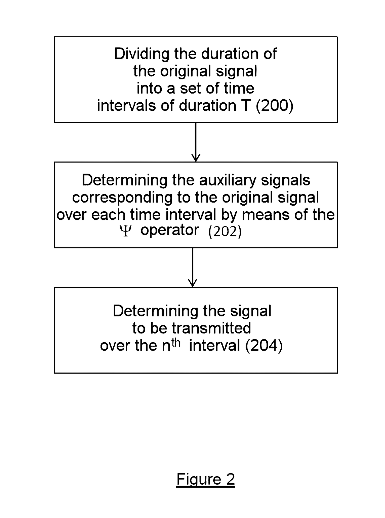
[0091]In the division and association steps 200 and 204, each time interval of duration T may again be divided into 2M sub-intervals, denoted by U−M, . . . , U1, . . . , UM, separated by short guard intervals (for example of the order of 1 / 10 of the duration of the intervals Uk) with durations increasing by |k|, as illustrated in the diagram of FIG. 3.
[0092]In step 202, the operator W is then chosen such that the value of the auxiliary signal W(x) (t) over each sub-interval Uk (for t ∈ to Uk) is dependent on:
[0093]the value of the initial signal x(t) over the sub-interval U−k (and vice versa), after time reversal (by replacing t by −t);
[0096]In particular, the value of the auxiliary signal Ψ(x)( ) at a time (T / 2+t), for t belonging to a sub-interval Uk (for t ∈ to Uk), may be dependent on the product between the value of the initial signal x( )at time (T / 2−t), on the phase exp j.βk and on the value of the amplitud...
second embodiment
[0138]Step 204 may subsequently be implemented as described above with reference to FIG. 2 (adding the auxiliary signal multiplied by the symbol whose amplitude and / or phase carries the information and, if applicable, by a gain α). Furthermore, the reception method, such as described with reference to FIG. 9, may be applied similarly in this
[0139]FIG. 16 illustrates one exemplary embodiment of steps 200 and 202, according to the second embodiment. This figure shows:
[0140](a) the initial signal x(t) over an interval of duration T, divided into three sub-intervals U1, U2, U3;
[0141](b) the signal after permutation of the signals over the sub-intervals: the signal over U1 is permuted with the section of signal over U2, the signal over U2 is permuted with the section of signal over U1 and the signal over U3 is permuted with the section of signal over U3 (the permutation may then be denoted by (1,2,3)→(2,1,3));
[0142](c) the signal after time reversal over the sub-intervals 2 and 3, then a...
PUM
Abstract
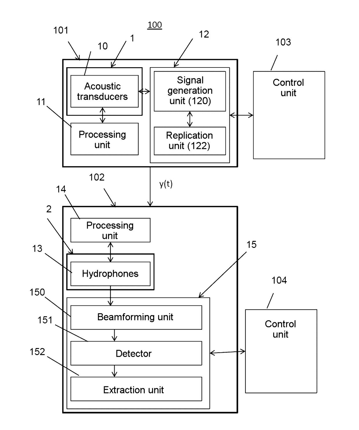
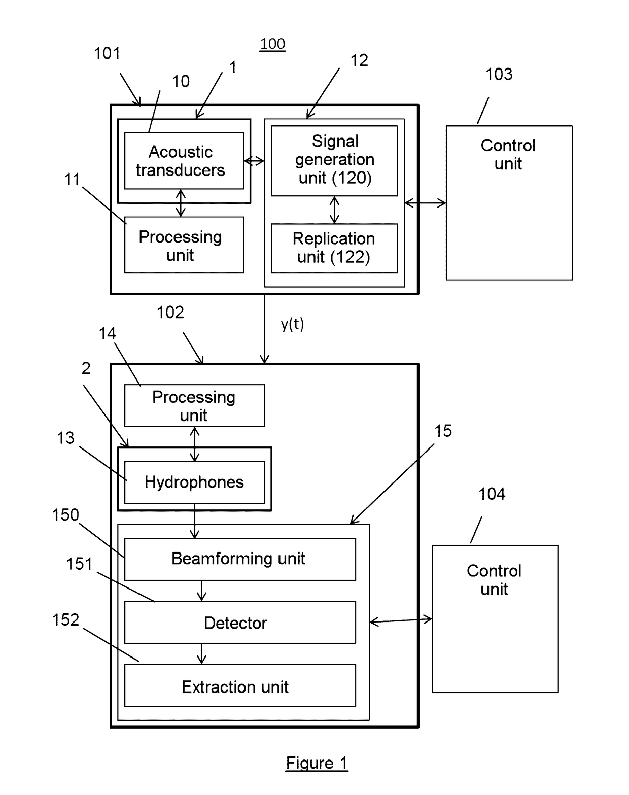
A transmitter device comprises a transmission antenna with at least one transducer and one signal generation unit for generating an acoustic communication signal to be transmitted to a receiver device including hidden information, wherein the signal generation unit is configured to previously record an original acoustic signal, the signal generation unit capable of generating the communication signal to be transmitted by adding, to an initial signal x(t) derived from the original signal, an auxiliary signal previously multiplied by at least one symbol, the symbol having a phase and / or an amplitude carrying the hidden information and the auxiliary signal calculated from the initial signal by a chosen transformation operator which depends on a steganographic key.
Description
CROSS-REFERENCE TO RELATED APPLICATIONS[0001]This application is a National Stage of International patent application PCT / EP2015 / 063861, filed on Jun. 19, 2015, which claims priority to foreign French patent application No. FR 1401400, filed on Jun. 20, 2014, the disclosures of which are incorporated by reference in their entirety.FIELD OF THE INVENTION[0002]The invention generally relates to acoustic communications, and, in particular, to a method and a system for discreet submarine acoustic communications.BACKGROUND[0003]Discreet submarine acoustic communication systems transmit acoustic communication signals (audio streams) to target receivers such that these signals are not detected by third parties or, if they are detected by third parties, are considered thereby to be an unremarkable component of ambient noise.[0004]Multiple solutions have been proposed in the past for hiding the information in an audio stream, for example in order to hide short messages of SMS (short message ...
Claims
Application Information
Patent Timeline
Application Date:The date an application was filed.
Publication Date:The date a patent or application was officially published.
First Publication Date:The earliest publication date of a patent with the same application number.
Issue Date:Publication date of the patent grant document.
PCT Entry Date:The Entry date of PCT National Phase.
Estimated Expiry Date:The statutory expiry date of a patent right according to the Patent Law, and it is the longest term of protection that the patent right can achieve without the termination of the patent right due to other reasons(Term extension factor has been taken into account ).
Invalid Date:Actual expiry date is based on effective date or publication date of legal transaction data of invalid patent.

