Method of manufacturing a rotary-type physical shield purifier

a technology of physical shield and purifier, which is applied in the direction of soldering apparatus, separation processes, fencing wire, etc., can solve the problems of purifier pan twisting and deformation, deviating from the state of the purifier, and affecting the service life of the purifier, so as to achieve high up-to-standard rate, high stability, and long service life

Inactive Publication Date: 2017-06-01
HU DUANZHI
View PDF3 Cites 0 Cited by
  • Summary
  • Abstract
  • Description
  • Claims
  • Application Information

AI Technical Summary

Benefits of technology

[0005]In order to address the above problems, the present invention provides the society with a method for manufacturing a rotary physical shielding purifier, and the rotary physical shielding purifier manufactured the manufacturing method has the advantages of long service life, high up-to-standard rate, high stability, high purification efficiency, low production cost and the like.
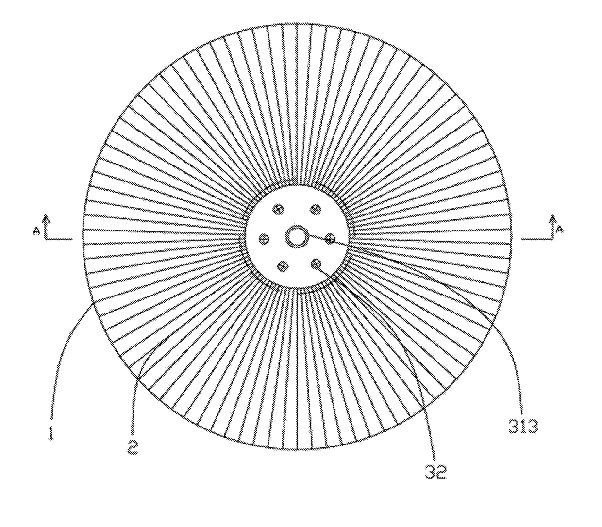
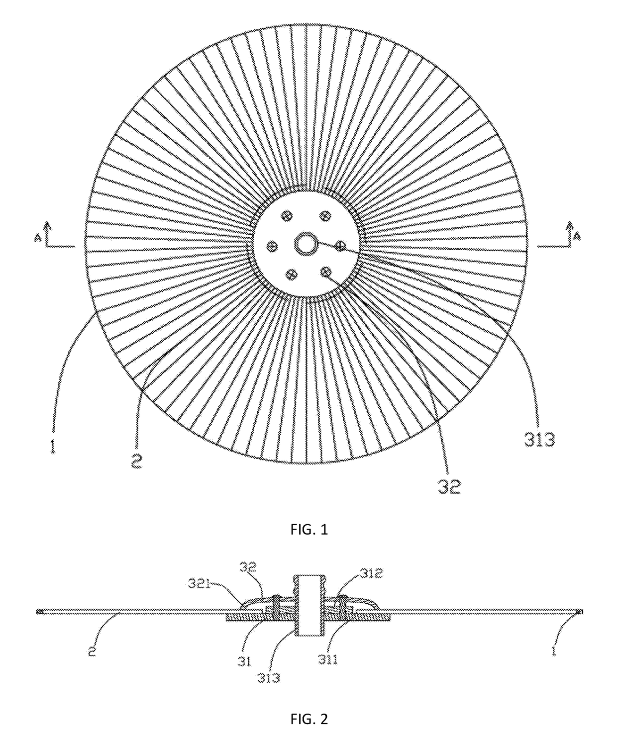
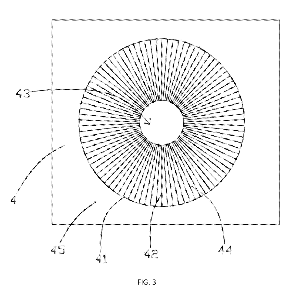
[0024]In the present invention, first of all, the contact parts between the spokes and the outer rim are firmly welded, and the pressing die is pressed on the spokes, such that the spokes will not camber and are maintained in the same plane all the time during welding; then, the inner ends of the spokes are fixed between the central clamp base and the central clamp gland, thus thoroughly preventing the spokes from twisting and cambering occurred in the product manufactured with other methods such as two ends welding or other connecting methods, such that the spokes are in the same plane, namely the whole purifier pan is maintained in the same plane. Furthermore, the spokes will neither displace even if being used in a high temperature environment for a long time, nor in different planes because the spokes become bigger in the axial direction. Therefore, the present invention will not reduce the purification capability for intercepting the particulate matters in the air, will not generate noises or cause mechanical damage, and has the advantages of long service life, high up-to-standard rate, high stability, high purification efficiency, low production cost and the like.

Problems solved by technology

The defects of the dynamic physical shielding purifier, manufacturing method and special fixture are obvious, because in the manufacturing method, the two ends of the spokes are respectively fixedly connected with the wheel hub and the fixing ring via a welder or a super glue; the welder will generate heat when in use, and the generated heat lengthens the axial length of the spokes, causing the middle of the spokes to camber, and the whole purifier pan to twist and deform, such that the spokes can not be maintained in the same plane, thus severely deviating the purifier from the state required by the purification theory, and greatly reducing the overall purification efficiency of the dynamic physical shielding purifier.
Furthermore, the twisted and deformed purifier is dynamically unbalanced, and will generate noises and mechanical damage during operation.
Since the spokes are fixed by a super glue and generally operates in a high temperature environment, the super glue is easy to lose stickiness, with the result that the spokes become loose or detach from the wheel hub and / or the fixing ring.
Therefore, the dynamic physical shielding purifier manufactured with the manufacturing method has a low up-to-standard rate, greatly wastes resources, and has the problems of short service life, low stability, high production cost and the like.

Method used


Image

  • Method of manufacturing a rotary-type physical shield purifier
  • Method of manufacturing a rotary-type physical shield purifier
  • Method of manufacturing a rotary-type physical shield purifier

Examples


Embodiment Construction

[0032]It shall be appreciated that in the description of the present invention, the direction or position relationships indicated by the terminologies “central”“on”, “under”“front”“back”, “left”, “right” and the like are the direction or position relationships as shown in the figures, are only intended to facilitate and simplify the description of the present invention, but not to indicate or imply that the indicated devices or elements must be at a specific position or be constructed and operated in a specific manner, which shall not be understood as limits to the present invention. In addition, the terminologies “first” and “second” are only used for the purpose of description, but not for indicating or implying relative importance.

[0033]It shall be noted that in the description of the present invention, unless otherwise stated or defined, the terminologies “install”, “connect” and “connection” shall be interpreted broadly, for example, the “connection” can be fixed connection, de...


PUM

PropertyMeasurementUnit
diameteraaaaaaaaaa
diameteraaaaaaaaaa
circumferenceaaaaaaaaaa

Abstract

A method for manufacturing a rotary physical shielding purifier, comprising the following steps: (1) respectively placing an outer rim, spokes and a central clamp base in an outer rim groove, spoke grooves and a central hole, and pressing a pressing die on the spokes; (2) using a welder to weld the contact parts between the spokes and the outer rim; (3) installing a central clamp gland on the central clamp base; and (4) separating the pressing die from a clamping die, and taking the finished product out.

Description

[0001]This application is the U.S. national phase of International Application No. PCT / CN2015 / 082585 Filed on 27 Jun. 2015 which designated the U.S. and claims priority to Chinese Application Nos. CN 201410335346.7 filed on 15 Jul. 2014, the entire contents of each of which are hereby incorporated by reference.FIELD OF THE INVENTION[0002]The present invention relates to a component of a device for dedusting and purifying air, in particular to a method for manufacturing a rotary physical shielding purifier using a physical method to remove the particulate matters (mainly liquid particulates) in exhaust air.BACKGROUND OF THE INVENTION[0003]In order to purify the air and remove the particulate pollutants in the air, the researchers invent a dynamic physical shielding purifier in recent years, e.g. the[0004]Chinese Patent Authorized Announcement No. CN 100591405C, which discloses a dynamic physical shielding purifier, manufacturing method and special fixture, wherein the disclosed dynam...

Claims


Application Information

Patent Timeline
Patent Type & Authority Applications(United States)
IPC IPC(8): B01D45/14B21F29/00
CPCB21F29/00B01D45/14B21F39/00B23K1/00
Inventor HU, DUANZHI
Owner HU DUANZHI
Why Eureka
Try Eureka