Position detecting sensor

Active Publication Date: 2017-06-01
SMC CORP
View PDF7 Cites 0 Cited by
  • Summary
  • Abstract
  • Description
  • Claims
  • Application Information

AI Technical Summary

Benefits of technology

The present invention aims to provide a position detecting sensor that can be easily and efficiently mounted onto an actuator, even in narrow operating spaces. The mounting member is inserted into the sensor attachment groove from one end of the actuator, allowing the position detecting sensor to be securely positioned during mounting. This results in a simple and efficient mounting process, improving the overall performance of the position detecting sensor.

Problems solved by technology

Therefore, an improvement in operational efficiency is not easily achieved, while additionally, constraints are imposed such as requiring a large operating space near the axial end of the cylinder.

Method used


Image

  • Position detecting sensor
  • Position detecting sensor
  • Position detecting sensor

Examples


Embodiment Construction

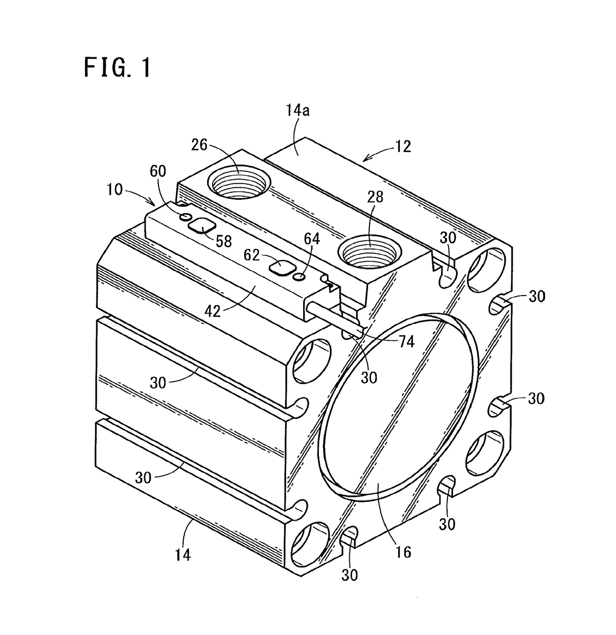
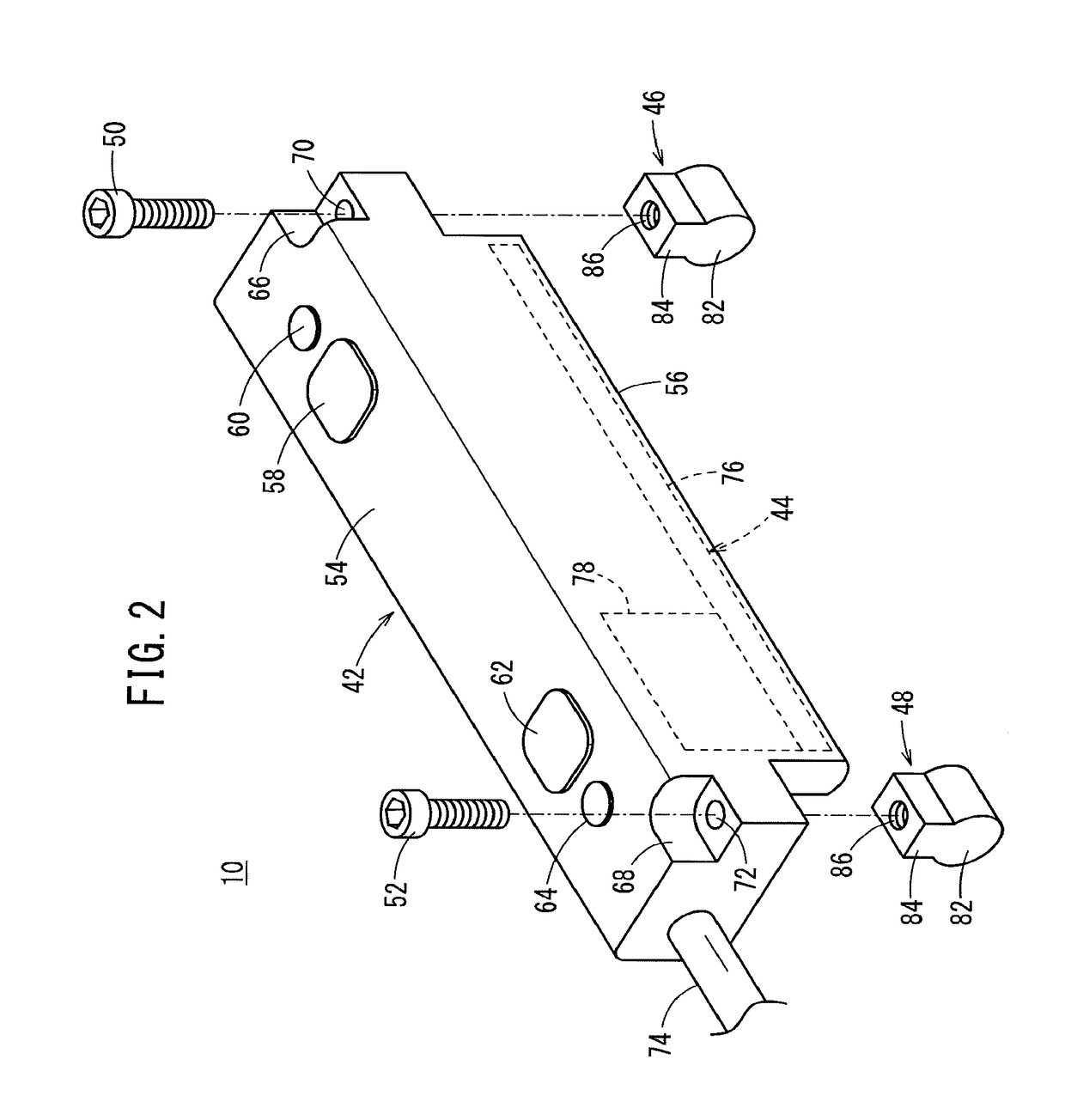
[0032]Below, a preferred embodiment concerning a position detecting sensor according to the present invention in relation to a cylinder device on which the positioning detecting sensor is mounted will be described in detail with reference to the accompanying drawings.

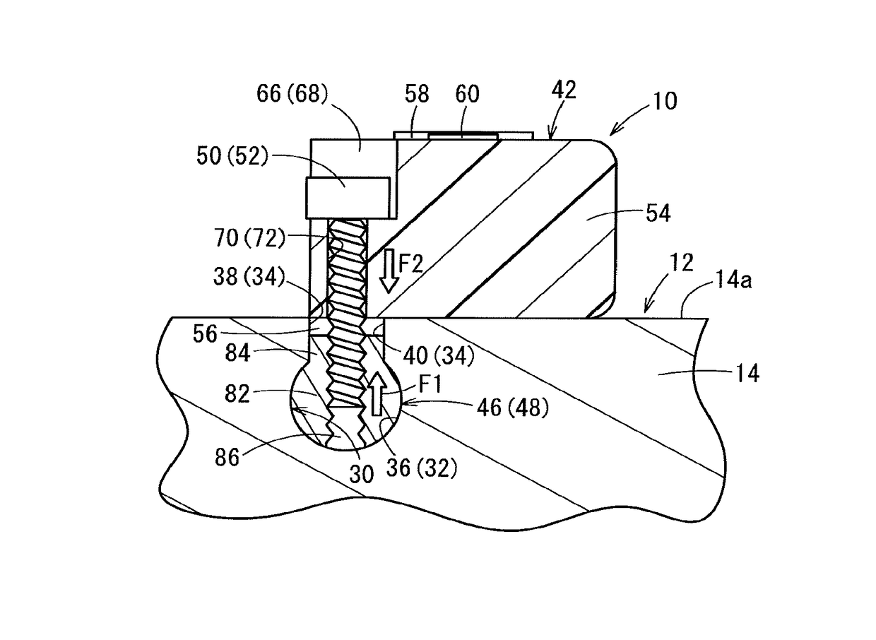
[0033]At first, the basic configuration of a cylinder device (actuator) 12 will be described. As shown in FIG. 1, the cylinder device 12 is equipped with a metallic cylinder tube 14 formed in a tubular shape, and a pair of end plates 16 that close the openings on ends in the axial direction of the cylinder tube 14.

[0034]A non-illustrated piston (displaceable body), which is displaced along the axial direction of the cylinder tube 14 under the supply of a pressure fluid, is disposed in an interior hole of the cylinder tube 14, and a non-illustrated piston rod is connected to the piston. An annular magnet, not shown, is mounted on an outer circumferential surface of the piston.

[0035]The cylinder tube 14 includes an outer ...


PUM


Abstract

A position detecting sensor is mounted in a sensor attachment groove formed in a cylinder device and having a wide portion and a narrow portion. Mounting members each include a mounting member main body positioned in the wide portion having a width dimension larger than a groove width of the narrow portion, and an extension extending from the mounting member main body and positioned in the narrow portion. The housing and the mounting members are connected by connecting bolts, whereby a portion of the cylinder device is retained between the housing and the mounting members.

Description

CROSS-REFERENCE TO RELATED APPLICATION[0001]This application is based upon and claims the benefit of priority from Japanese Patent Application No. 2015-234540 filed on Dec. 1, 2015, the contents of which are incorporated herein by reference.BACKGROUND OF THE INVENTION[0002]Field of the Invention[0003]The present invention relates to a position detecting sensor which is mounted in a sensor attachment groove that opens on a side surface of an actuator and extends along an axial direction to at least one end surface of the actuator.[0004]Description of the Related Art[0005]Conventionally, for detecting the position of a piston in the interior of a cylinder that constitutes part of an actuator, a magnet is installed on the piston, and a magnetic sensor that detects magnetism from the magnet is arranged on an outer side of the actuator. The piston is reciprocally operated under the supply of a pressure fluid, and the position of the piston is confirmed by magnetism from the magnet that i...

Claims


Application Information

Patent Timeline
IPC IPC(8): F15B19/00G01D5/12F15B11/08G01D11/24
CPCF15B19/005G01D11/245F15B2211/857F15B11/08G01D5/12F15B15/2815F15B15/2869F15B15/2861F15B15/2892G01D11/30
Inventor MANDOKORO, JIRO
Owner SMC CORP
Why Eureka
Try Eureka