
Ripple monitoring

a technology of ripple and monitoring system, applied in the direction of power supply testing, instruments, code conversion, etc., can solve the problems of affecting the ability of the power supply to meet one or more specifications, affecting the operation of the affected power supply, and particularly problematic ageing electrolytic capacitors,

Active Publication Date: 2017-06-01
ANALOG DEVICES INT UNLTD
View PDF8 Cites 11 Cited by
  • Summary
  • Abstract
  • Description
  • Claims
  • Application Information

AI Technical Summary

Benefits of technology

The patent text describes a circuit that can monitor the ripple (ripple) in a power supply. This circuit can detect when there is a problem with the power supply by measuring the ripple and analyzing it. The circuit can quantize the amplitude of the ripple and count how many times it occurs at different levels. By measuring and analyzing the ripple, the circuit can help identify and troubleshoot problems with the power supply. Overall, this circuit helps to improve the reliability and efficiency of power supplies.

Problems solved by technology

Electrical components in such power supplies may degrade which, in turn, may impair the ability of the power supplies to meet one or more specifications.
Ageing electrolytic capacitors, for example, can be particularly problematic.
This may cause the affected power supply to operate unreliably.
Operating from an out-of-spec power supply may cause random failures, such as occasional memory loss, false calculations, tripping of watchdog timers, and / or a need to reset and / or reboot the entire system from time to time.
Such failures may occur rarely at first, and only under specific temperature, line or load conditions.
They may be hard or almost impossible to catch by common power supply supervisor ICs, as their trip points may be set to detect out-of-spec power supply voltages.
But by then, it may be too late, especially for high reliability and / or high availability systems.
However, this approach to detect degrading power supplies before the system fails can be a tightrope walk at best, between false alarms happening too often, and not being able to detect an unfolding problem soon enough.
This may be due to the mixed nature of the power supply ripple, which may have ripple components caused by switching power supply operation and by varying or periodic load currents and / or load current transients, and the two state nature of any comparator output signal not being able to convey much supporting information.

Method used


Image

  • Ripple monitoring
  • Ripple monitoring
  • Ripple monitoring

Examples


Embodiment Construction

[0026]Illustrative embodiments are now described. Other embodiments may be used in addition or instead. Details that may be apparent or unnecessary may be omitted to save space or for a more effective presentation. Some embodiments may be practiced with additional components or steps and / or without all of the components or steps that are described.

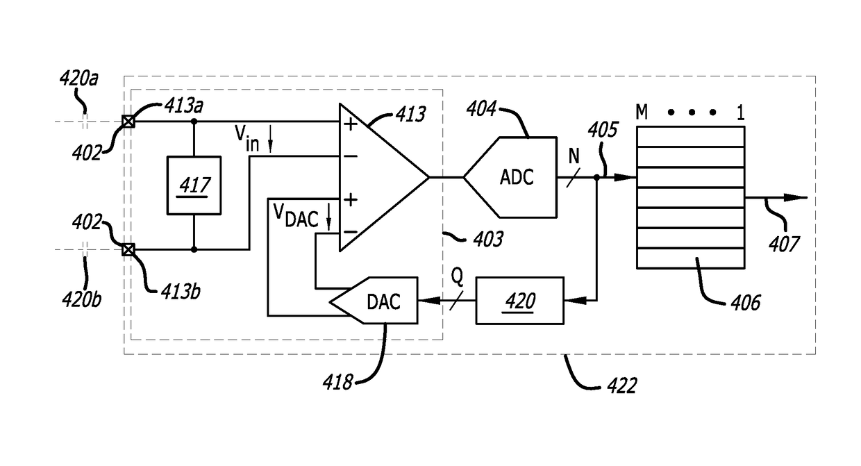
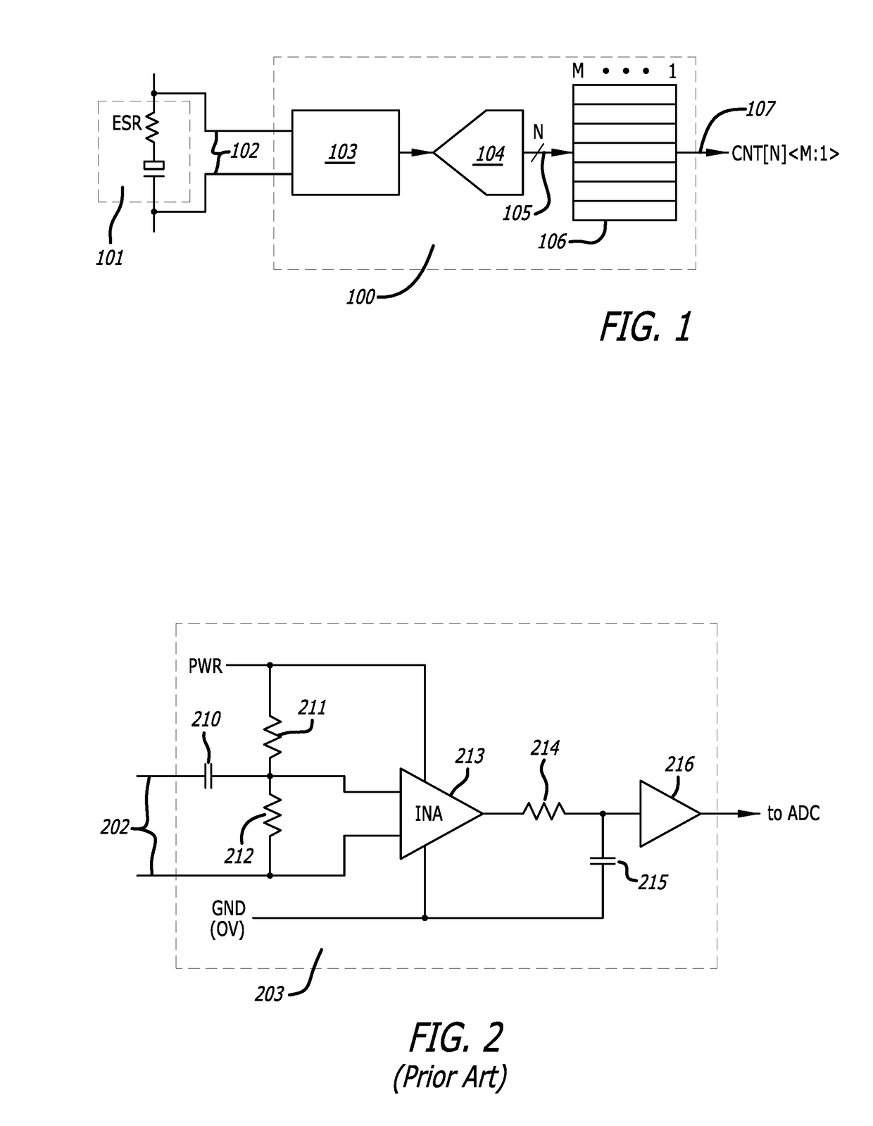
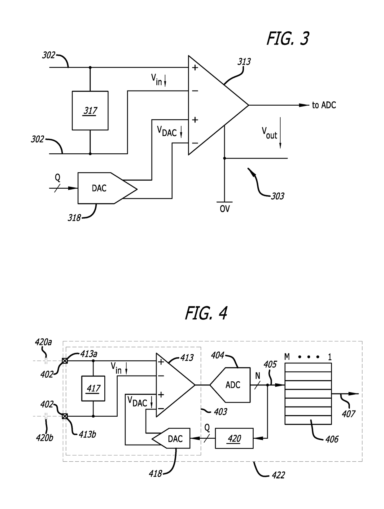
[0027]FIG. 1 illustrates an example of a ripple monitoring circuit 100. The ripple monitoring circuit 100 may collect amplitude statistics of voltage ripple in a ripple signal 102 from a power supply whose operational fitness is to be monitored, such as the signal across an output capacitor or other output of the power supply. This circuit may be part of an integrated circuit (IC).

[0028]The ripple monitoring circuit 100 may be coupled to an electrolytic capacitor 101 in the power supply, which might cause failure of the power supply due to ageing properties, such as an increase in its equivalent series resistance (ESR). This may manifest i...


PUM


Abstract

A ripple monitoring circuit may generate information indicative of a failing component in a power supply. At least one input may receive a ripple signal from the power supply that has a ripple component. A quantization circuit may repeatedly quantize the amplitude of the ripple component. A ripple amplitude statistics counter bank may count and store the number of times that different quantized amplitudes or different ranges of quantized amplitudes of the ripple component occurred.A ripple monitoring circuit may generate information about a power supply. At least one input may receive a ripple signal from the power supply that has a ripple component. A ripple measurement circuit may measure a characteristic of the ripple component. A storage circuit may store information about the measurement. A comparison circuit may compare information stored in the storage circuit with a threshold value and indicate when the stored information meets or exceeds this threshold value.

Description

CROSS-REFERENCE TO RELATED APPLICATION[0001]This application is based upon and claims priority to U.S. provisional patent application 62 / 261,032, entitled “System and Method for Ripple Monitoring,” filed Nov. 30, 2015, attorney reference 081318-0950. The entire content of this application is incorporated herein by reference.BACKGROUND[0002]Technical Field[0003]This disclosure relates to ripple monitoring systems and methods that may be embedded in an integrated circuit (“IC”). The ripple monitoring may be used to monitor power supply operations.[0004]Description of Related Art[0005]Power supplies of high performance microprocessors or high density ASICs or FPGAs, commonly referred to as “switching power supplies,” may have demanding specifications for line and load regulation, load transient response, and / or residual ripple voltage caused by their inherent switching operation.[0006]Electrical components in such power supplies may degrade which, in turn, may impair the ability of the...

Claims


Application Information

Patent Timeline
Patent Type & Authority Applications(United States)
IPC IPC(8): G01R31/40H03M1/66G01R19/00H03M1/12
CPCG01R31/40G01R19/0084H03M1/66H03M1/12G01R31/42H03M1/1295
Inventor ENGL, BERNHARD HELMUTCHIACCHIA, ROBERTDOBKIN, ROBERT C.
Owner ANALOG DEVICES INT UNLTD
Features
  • Generate Ideas
  • Intellectual Property
  • Life Sciences
  • Materials
  • Tech Scout
  • Unparalleled Data Quality
  • Higher Quality Content
  • 60% Fewer Hallucinations
Learn More