Irregular shape display device having hole

a display device and irregular shape technology, applied in the field of irregular shape display devices, can solve the problems of more restrictive structure, more restrictive molding and dimensional design errors, etc., and achieve the effects of reducing luminance differences, improving dark portions, and enhancing image quality

Active Publication Date: 2017-06-01
LG DISPLAY CO LTD
View PDF7 Cites 15 Cited by
  • Summary
  • Abstract
  • Description
  • Claims
  • Application Information

AI Technical Summary

Benefits of technology

[0042]As described above, an irregular shape display having a hole according to an embodiment of the present disclosure may reduce a luminance difference between the front and the back of the hole, thereby improving a dark portion around the hole as well as blocking light leaked out between the light guide plate and the guide member.
[0043]Accordingly, the present disclosure provides an effect of enhancing image quality.

Problems solved by technology

Furthermore, the molding and dimensional design error is more restrictive in a structure to which the foregoing hook 51 is applied to an outer side of the lower cover 50 or the hook is applied to an inner side of the guide panel 45.

Method used


Image

  • Irregular shape display device having hole
  • Irregular shape display device having hole
  • Irregular shape display device having hole

Examples


first embodiment

[0066]FIG. 2 is a plan view illustrating an irregular shape display according to the present disclosure for an example.

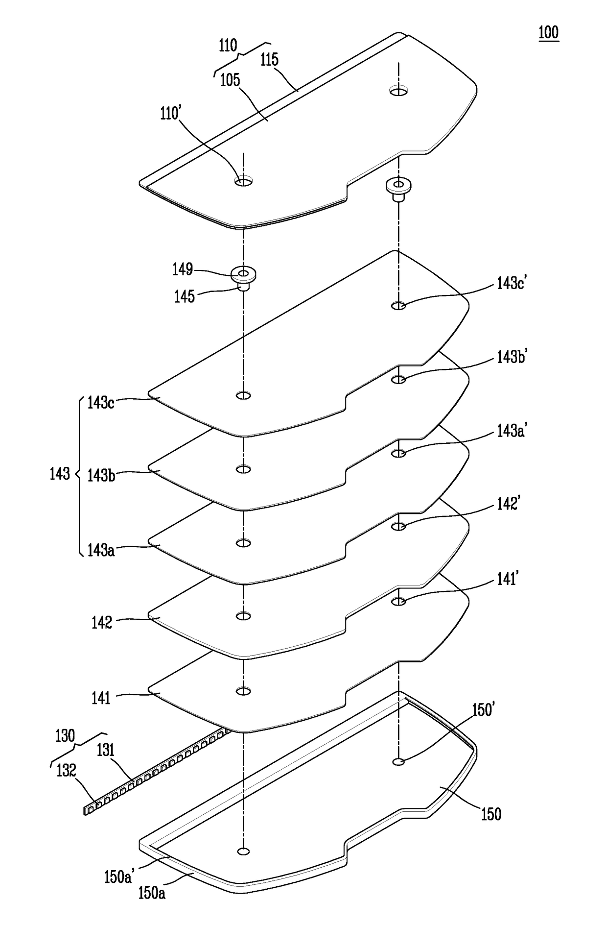
[0067]FIG. 3 is an exploded perspective view schematically illustrating the structure of the irregular shape display according to the first embodiment of the present disclosure illustrated in FIG. 2.

[0068]FIG. 4 is a view schematically illustrating the planar structure of a low cover in the irregular shape display according to the first embodiment of the present disclosure illustrated in FIG. 2.

[0069]FIG. 5 is a view schematically illustrating a cross-section taken along line A-A′ in the irregular shape display according to the first embodiment of the present disclosure illustrated in FIG. 4, and FIG. 6 is a view schematically illustrating a cross-section taken along line B-B′ in the irregular shape display according to the first embodiment of the present disclosure illustrated in FIG. 4. In other words, FIG. 5 illustrates a cross-section around a hole as an example...

second embodiment

[0147]FIG. 9 is a view schematically illustrating a partial cross-section of an irregular shape display according to the present disclosure.

[0148]Furthermore, FIG. 10 is a view schematically illustrating another partial cross-section of the irregular shape display according to the second embodiment of the present disclosure.

[0149]Here, FIG. 9 illustrates a cross-section around the hole as an example, and FIG. 10 illustrates a cross-section of an edge portion of the hole as an example.

[0150]Furthermore, the irregular shape display according to the second embodiment of the present disclosure illustrated in FIGS. 9 and 10 may have substantially the same configuration as that of the foregoing first embodiment of the present disclosure except for the liquid crystal panel being mounted on the reflection sheet.

[0151]Referring to FIGS. 9 and 10, the irregular shape display according to the second embodiment of the present disclosure may include a liquid crystal panel 210 in which liquid cry...

third embodiment

[0160]The reflector 241 is located between the lower cover 250 and a rear surface of the light guide plate 242. The reflector 241 performs the role of reflecting light from the light source and light from the light guide plate 242 to the side of the liquid crystal panel 210. Here, FIGS. 11 and 12 illustrate a case where a reflector 341 is formed in a shape of surrounding an edge side of a light guide plate 342 as an example, which will be explained more fully as a

[0161]Furthermore, the light source may be selected from any one of CCFL, HCFL, EEFL and LED, but may not be necessarily limited to this. Hereinafter, for the sake of convenience of explanation, a case where an LED array is used for the light source will be taken as an example.

[0162]The LED array is provided on a flexible printed circuit board such that a light exit surface thereof faces an incident surface of the light guide plate 242. In other words, the light source unit may include the flexible printed circuit board and...


PUM

PropertyMeasurementUnit
thicknessaaaaaaaaaa
sizeaaaaaaaaaa
sizeaaaaaaaaaa

Abstract

An irregular shape display having a hole according to the present disclosure may insert a cylinder-shaped guide member with the same material as that of a light guide plate within a hole to reduce a luminance difference between the front and the back of the hole, thereby improving a dark portion in the vicinity of the hole.
Furthermore, the present disclosure may attach a reflection sheet to an upper portion of the guide member to block light leaked out between the light guide plate and the guide member.

Description

CROSS-REFERENCE TO RELATED APPLICATIONS[0001]This application claims the benefit of Korean Patent Application No. 10-2015-0169205, filed in the Republic of Korea on Nov. 30, 2015, which is hereby incorporated by reference in its entirety.BACKGROUND[0002]Field of the Disclosure[0003]The present disclosure relates to a display device, and more particularly, to an irregular shape display (or non-tetragonal shaped display) having a hole.[0004]Description of the Background[0005]In recent information society, the importance of display (or display devices) is more emphasized as a visual information transmission medium, but their requirements such as low power consumption, thin profile, light weight, high picture quality should be satisfied in order to take the principal position in the future.[0006]Display devices can be divided into an emissive type display capable of spontaneously emitting light such as cathode ray tube (CRT), electro luminescence (EL), light emitting diode (LED), vacuum...

Claims


Application Information

Patent Timeline
Patent Type & Authority Applications(United States)
IPC IPC(8): G02F1/1333F21V8/00G02F1/1339
CPCG02F1/133308G02F2001/133317G02B6/005G02B6/0088G02F2201/56G02F1/13439G02F2201/121G02F2201/123G02F1/137G02F1/133514G02F1/1368G02F1/136286G02F2202/28G02F2001/133314G02F1/1339G02F1/1333G02F1/1335G02F1/133553G09F9/35B60K37/02B60K2370/152B60K2370/154B60K2370/698G02B6/0055G02F1/133615G02F2201/46G04G17/045G02F1/133322G02F1/133314G02F1/133317
Inventor AHN, SEUNGHYUNKIM, MIOK
Owner LG DISPLAY CO LTD
Why Eureka
Try Eureka