Timing device, electronic apparatus, and moving object

a technology of electronic equipment and time stamps, applied in the direction of electric digital data processing, instruments, generating/distributing signals, etc., can solve the problems of further increases in consumed current, achieve no increase in consumed current, increase the accuracy of time stamp data, and simple circuit configuration

Active Publication Date: 2017-06-01
SEIKO EPSON CORP
View PDF0 Cites 8 Cited by
  • Summary
  • Abstract
  • Description
  • Claims
  • Application Information

AI Technical Summary

Benefits of technology

[0006]A first advantage of some aspects of the invention is to provide a timing device capable of performing timing action on a 1 / 1000-second basis in a simple circuit configuration with almost no increase in consumed current. A second advantage of some aspects of the invention is to increase the accuracy of time stamp data representing the time when an event is detected. A third advantage of some aspects of the invention is to provide an electronic apparatus, a moving object, and other apparatus using the timing device.

Problems solved by technology

Direct application of the timing method described above to timing action on a 1 / 1000-second basis, however, requires a clock signal having a frequency higher than 4096 Hz or requires a complicated circuit configuration due to a complicated counting condition and further increases consumed current.

Method used


Image

  • Timing device, electronic apparatus, and moving object
  • Timing device, electronic apparatus, and moving object
  • Timing device, electronic apparatus, and moving object

Examples


first embodiment

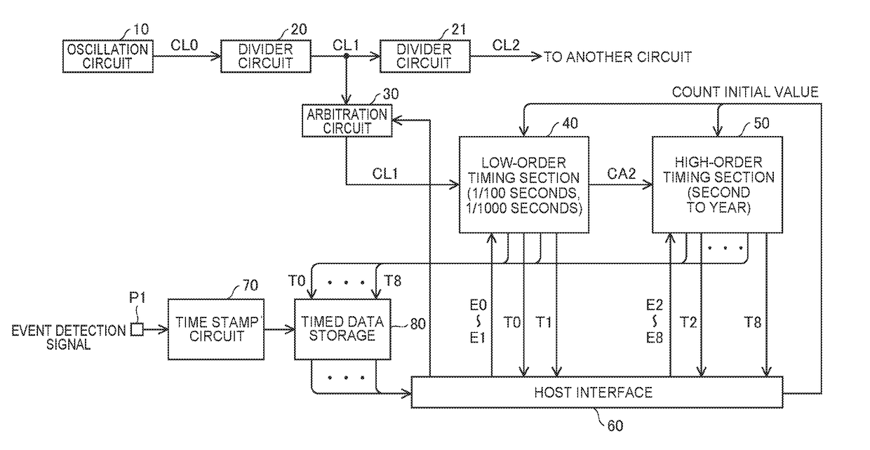
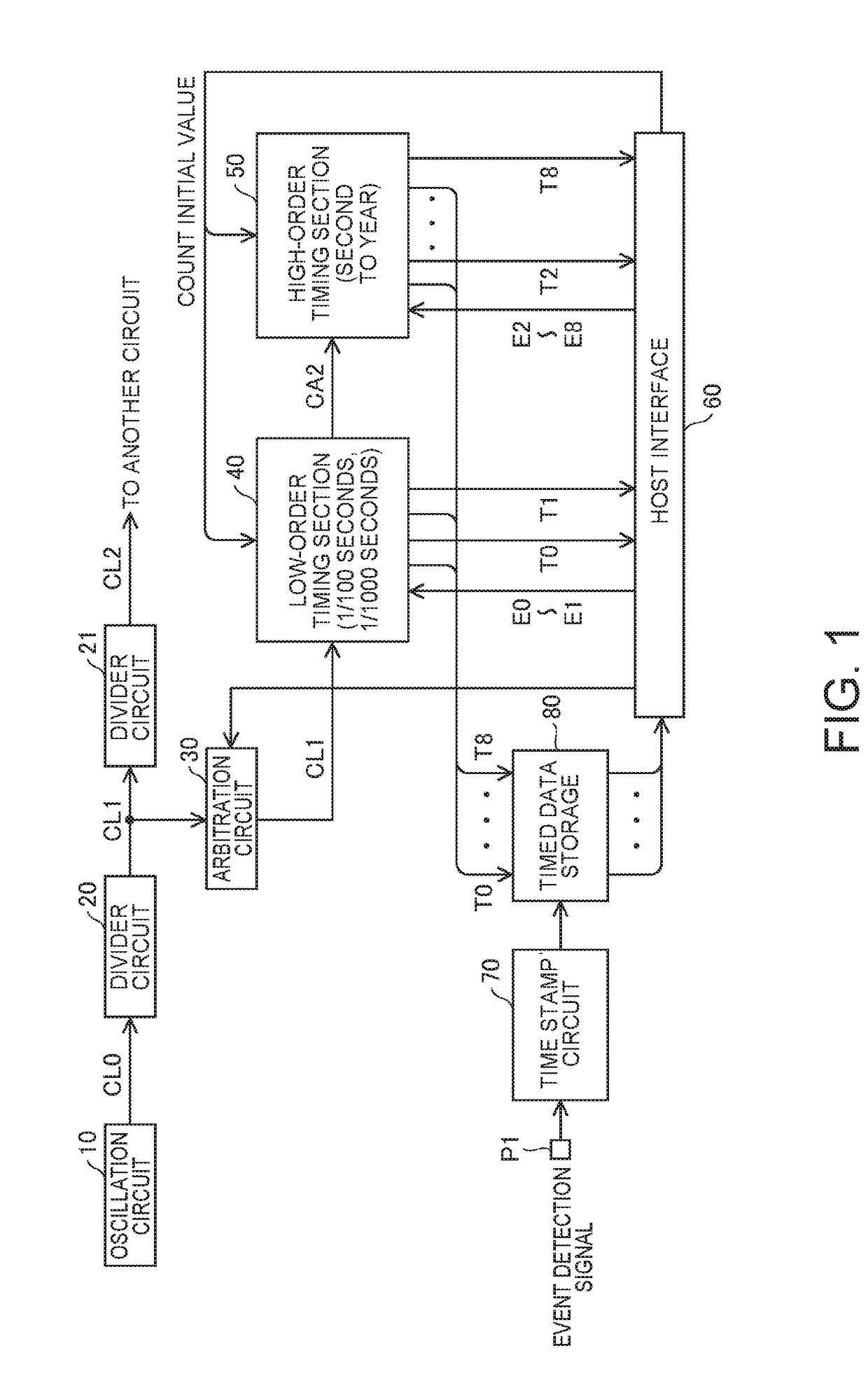
[0027]FIG. 1 is a block diagram showing an example of the configuration of a timing device according to a first embodiment of the invention. The timing device has the function of a real-time clock (RTC) that performs timing action in synchronization with a clock signal to generate timed data.

[0028]The timing device includes an oscillation circuit 10, divider circuits 20 and 21, an arbitration circuit 30, a low-order timing section 40, a high-order timing section 50, and a host interface 60 and may further include a time stamp circuit 70 and a timed data storage 80, as shown in FIG. 1. Key portions of the timing device may be built in a semiconductor device (IC).

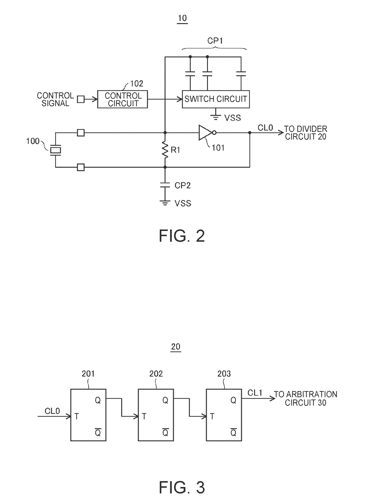
[0029]The oscillation circuit 10 performs oscillation action to generate an oscillation-source clock signal CL0, for example, having a frequency of 32768 Hz (215 Hz). The generation of the oscillation-source clock signal CL0 having a frequency of a power of 2 also allows division of the oscillation-source clock signal CL0 to ...

second embodiment

[0086]FIG. 6 is a block diagram showing an example of the configuration of a timing device according to a second embodiment of the invention. In the second embodiment, the divider circuit 21 divides the divided clock signal CL1 outputted from the arbitration circuit 30 to generate the divided clock signal CL2 having a frequency of 1 Hz, and the high-order timing section 50 performs timing action in synchronization with the divided clock signal CL2. Further, an arbitration circuit 31 is added to the first embodiment, as shown in FIG. 6. With regard to the other points, the second embodiment may be the same as the first embodiment.

[0087]The oscillation circuit 10 performs oscillation action to generate the oscillation-source clock signal CL0, for example, having the frequency of 32768 Hz. The divider circuit 20 divides the oscillation-source clock signal CL0 to generate the divided clock signal CL1 having the frequency of 4096 Hz. The divider circuit 21 divides the divided clock signa...


PUM


Abstract

A timing device includes a counter that performs counting action in synchronization with pulses in a clock signal to generate a 6-bit count value representing decimal numbers “0” to “39” in each count cycle in order to perform counting action on a 1/100-second basis and an output control circuit that outputs upper 4 bits of the count value generated by the counter as 4-bit timed data representing time on a 1/1000-second basis.

Description

BACKGROUND[0001]1. Technical Field[0002]The present invention relates to a timing device that performs timing action in synchronization with a clock signal to generate timed data. The present invention further relates to an electronic apparatus, a moving object, and other apparatus using the timing device.[0003]2. Related Art[0004]A timing device used in a stopwatch or any other timepiece has the function of performing timing action on a 1 / 100-second basis. For example, repeating a 41-count cycle by 96 times and a 40-count cycle by 4 times in synchronization with a clock signal of 4096 Hz amounts to 100 count cycles in total, during which 1 second elapses, as described in the data sheet of Low-Voltage SPI / 3-Wire RTCs with Trickle Charger (MAXIM INTEGRATED, on page 15). Therefore, each of the 41-count periods or the 40-count periods contains an error to some extent but accurately corresponds to the period of 1 / 100 seconds in the long run.[0005]Direct application of the timing method ...

Claims


Application Information

Patent Timeline
Patent Type & Authority Applications(United States)
IPC IPC(8): G06F1/12
CPCG06F2221/2151G06F1/12G06F1/14
Inventor KAMIYAMA, MASAYUKIYONEYAMA, TSUYOSHISHIROTORI, TORU
Owner SEIKO EPSON CORP
Why Eureka
Try Eureka