Emergency-egress, zip-line system and method

Active Publication Date: 2017-06-08
ZIPHLDG
View PDF4 Cites 9 Cited by
  • Summary
  • Abstract
  • Description
  • Claims
  • Application Information

AI Technical Summary

Benefits of technology

[0016]The procedure of operation is sufficiently simplified that there is comparatively little to remember. Thus, a simple process, straightforward training, and riders may move quickly in an emergency situation t

Problems solved by technology

Frequency of use, rider ability, panic, skill, comfort with speed, or the like, and the presence of multiple riders accessing, launching, and riding seats simultaneously create risks affecting operation and safety.
Overweighting a catenary near a single location distorts its shape, altering clearance above a deck or other surface therebelow.
This creates problems for riders needing to stage loading and launc

Method used


Image

  • Emergency-egress, zip-line system and method
  • Emergency-egress, zip-line system and method
  • Emergency-egress, zip-line system and method

Examples


Embodiment Construction

[0045]It will be readily understood that the components of the present invention, as generally described and illustrated in the drawings herein, could be arranged and designed in a wide variety of different configurations. Thus, the following more detailed description of the embodiments of the system and method of the present invention, as represented in the drawings, is not intended to limit the scope of the invention, as claimed, but is merely representative of various embodiments of the invention. The illustrated embodiments of the invention will be best understood by reference to the drawings, wherein like parts are designated by like numerals throughout.

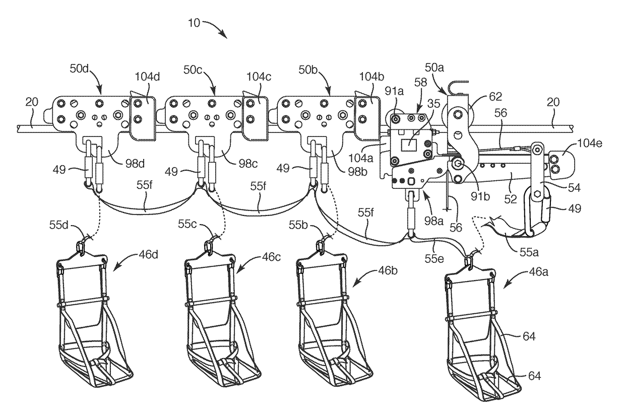
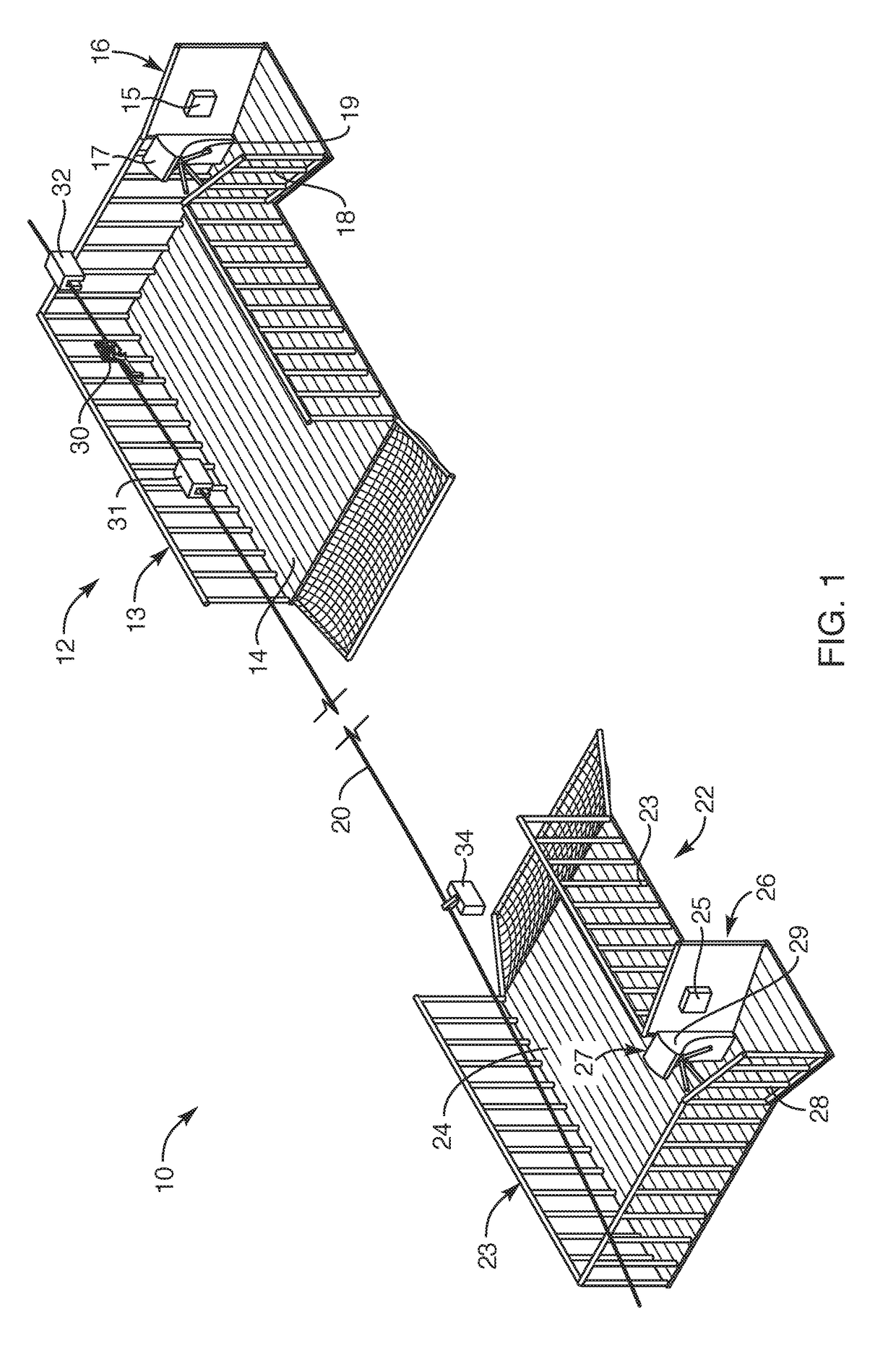
[0046]A zip line may extend as a catenary, as defined in the engineering art. The term “catenary” is understood by repair to any textbook on structural mechanics or engineering nomenclature. The catenary extends freely between end supports. It may suspend from an upper anchor point to a lower anchor point, the decline of the lin...


PUM


Abstract

Emergency egress systems carry multiple riders simultaneously accessing zip line catenary from higher, inaccessible, working locations to lower, safer areas. Hangers above the track line suspend trolleys to avoid weighting the catenary unduly at the high end, which might otherwise alter (reduce) clearance distances and safety of riders above a launch platform (deck). Catenary shape is controlled against approaching a launch deck by sequencing the release from the hangers of each trolley to roll along the catenary with its own rider. Autonomous braking, inter-trolley bumpers, and vertical stabilizers enable each rider to quickly occupy a seat (harness, etc.) and launch onto the track line, unconcerned with riders ahead or behind until underway. Multiple trolleys may thus load, launch, and in close proximity on a single line, regardless of the total weight of multiple riders.

Description

RELATED APPLICATIONS[0001]This application: is a continuation in part of U.S. patent application Ser. No. 15 / 354,866, filed Nov. 17, 2016, which claims the benefit of Provisional Patent Application Ser. No. 62 / 257,610, filed Nov. 19, 2015; and is a continuation in part of U.S. patent application Ser. No. 14 / 923,708, filed Oct. 27, 2015, all of which are hereby incorporated by reference. This application also incorporates herein by reference the following applications and patents: U.S. patent application Ser. No. 14 / 451,932, filed Aug. 5, 2014; U.S. patent application Ser. No. 14 / 711,465, filed May 13, 2015; U.S. Provisional Patent Application Ser. No. 62 / 058,544, filed Oct. 1, 2014; and U.S. patent application Ser. No. 14 / 923,708, filed Oct. 27, 2015. Moreover, this application hereby incorporates herein by reference U.S. Pat. No. 7,637,213, issued Dec. 29, 2009; U.S. Pat. No. 7,966,940, issued Jun. 28, 2011; U.S. Pat. No. 7,299,752, issued Nov. 27, 2007; U.S. Pat. No. 7,404,360, is...

Claims


Application Information

Patent Timeline
IPC IPC(8): A62B1/20F16D63/00B61B12/00B61B7/00B61H9/02
CPCA62B1/20B61B7/00F16D63/008B61B12/002B61H9/02A63G21/22A63G21/20
Inventor CYLVICK, ERIC S.
Owner ZIPHLDG
Why Eureka
Try Eureka