Anchor structure, and liquefied natural gas storage tank comprising said anchor structure

a technology of anchor structure and liquefied natural gas storage tank, which is applied in the direction of threaded fasteners, bolts, containers, etc., can solve the problems of complex structure of connecting the secondary sealing wall difficult installation of the heat insulating wall, and complex structure of the lng storage tank connection wall. , to achieve the effect of improving the strength of the anchor structure and relieving stress concentration

Active Publication Date: 2017-06-08
KC LNG TECH CO LTD
View PDF2 Cites 15 Cited by
  • Summary
  • Abstract
  • Description
  • Claims
  • Application Information

AI Technical Summary

Benefits of technology

[0049]According to the present invention, a joint of the anchor member joined to the sealing wall can horizontally slide, thereby actively coping with deformation of a hull, and a lower portion of an anchor support rod is movable up and down, thereby relieving stress concentration on a heat insulation system under the load of LNG.
[0050]In addition, according to the present invention, a metal reinforcement plate is interposed between a first anchor lower plate and a second anchor lower plate, thereby improving strength of an anchor structure.

Problems solved by technology

In the typical LNG storage tank shown in FIG. 1, the heat insulating wall structure is composed of the primary and secondary heat insulating walls and the primary and secondary sealing walls and thus has a complicated structure.
In addition, the structure for connecting the secondary sealing wall of the LNG storage tank is complicated, and installation of the heat insulating wall is not easy.
Further, there is a possibility that sealing reliability of the secondary sealing wall is reduced (LNG leakage), since the structure of a connection of the anchor structure or the secondary sealing wall is complicated, and installation of the anchor structure or the secondary sealing wall is difficult.
In the typical LNG storage tank shown in FIGS. 2 and 3, since the joints and securing portion of the anchor member are not movable, it is difficult to cope with deformation of the hull and to eliminate stress concentration on the heat insulation system subjected to the load of LNG.
In addition, there is a problem in that it is difficult to manufacture the anchor member due to the complicated shape thereof.

Method used


Image

  • Anchor structure, and liquefied natural gas storage tank comprising said anchor structure
  • Anchor structure, and liquefied natural gas storage tank comprising said anchor structure
  • Anchor structure, and liquefied natural gas storage tank comprising said anchor structure

Examples


Embodiment Construction

[0063]Hereinafter, embodiments of the present invention will be described with reference to the accompanying drawings. It should be noted that like components will be denoted by like reference numerals throughout the specification and the accompanying drawings. In addition, descriptions of details apparent to those skilled in the art will be omitted for clarity.

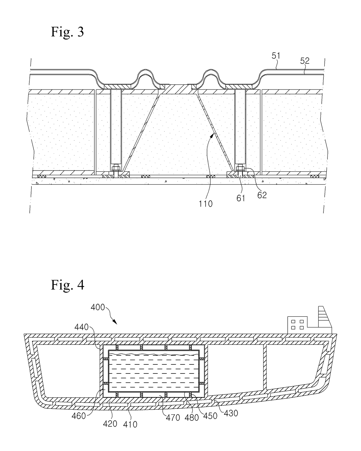
[0064]First, a structure of a ship having an LNG storage tank according to one embodiment of the present invention will be described with reference to FIGS. 4 and 5. FIG. 4 is a sectional view of an exemplary ship having an LNG storage tank according to one embodiment of the present invention and FIG. 5 is an enlarged sectional view of a portion of the LNG storage tank according to the embodiment of the present invention, more particularly, a heat insulating wall.

[0065]Referring to FIG. 4, the LNG storage tank according to the embodiment of the present invention may be installed in a ship 400, which is composed of a hull havi...


PUM

PropertyMeasurementUnit
distanceaaaaaaaaaa
constant distanceaaaaaaaaaa
anchor structureaaaaaaaaaa

Abstract

The present invention relates to an anchor structure able to actively cope with hull deformation, and to a liquid natural gas storage tank and a production method for a liquid natural gas storage tank comprising the anchor structure. According to one embodiment of the present invention, an anchor structure is provided wherein an anchor structure, for linking a sealing wall and an inner wall of a liquid natural gas storage tank, comprises: an anchor member adapted such that a joining part, which is joined to the sealing wall, can slide horizontally; and a thermally insulating material formed around the anchor member.

Description

TECHNICAL FIELD[0001]The present invention relates to an anchor structure and an LNG storage tank including the same.BACKGROUND ART[0002]Liquefied natural gas (LNG) is obtained by liquefying natural gas, one of the fossil fuels, and LNG storage tanks may be divided into onshore storage tanks installed on the ground or buried in the ground and mobile storage tanks installed in vehicles such as automobiles and ships, depending on installation location.[0003]Since LNG has a danger of explosion when exposed to impact and is kept under cryogenic conditions, a storage tank for LNG has a structure in which impact resistance and liquid tightness are firmly maintained.[0004]In addition, in contrast to onshore storage tanks where sloshing of LNG is negligible, LNG storage tanks installed in automobiles and ships should be able to withstand mechanical stress due to the sloshing. However, since LNG storage tanks installed on ships equipped with measures against mechanical stress can also be use...

Claims


Application Information

Patent Timeline
Patent Type & Authority Applications(United States)
IPC IPC(8): F17C13/08F16B5/02B65D90/06B63B25/16F17C1/12
CPCF17C13/08F17C13/082F17C13/083F16B5/02B63B25/16F17C1/12B65D90/06F17C13/081F17C2205/0192F16B33/004F17C3/00F17C2203/0333F17C2203/0604F17C2203/0619F17C2205/0119F17C2221/033F17C2225/0161F17C2225/033F17C2260/044F17C2270/0105
Inventor HAN, HAE CHULYOON, IHN SOOJIN, KYO KOOKOH, BYUNG TAEKCHO, YONG BUMCHOE, KUN HYUNG
Owner KC LNG TECH CO LTD
Why Eureka
Try Eureka