Pneumatic firing device

a firing device and pneumatic technology, applied in the direction of compressed gas guns, white arms/cold weapons, weapons, etc., can solve the problems of increasing manufacturing costs, affecting the operation efficiency of mechanical guns, and the user of mechanical guns not being able to quickly pull the trigger, etc., to achieve smooth operation, less malfunctions, and faster firing speed

Active Publication Date: 2017-06-08
SHEN LIANG CHI
View PDF24 Cites 6 Cited by
  • Summary
  • Abstract
  • Description
  • Claims
  • Application Information

AI Technical Summary

Benefits of technology

[0027]With features disclosed above, the present invention changes the pressure difference between the first chamber and the second chamber, controls the operation of the pressure release channel to push forward the delivery tube with pressured air, sending a pellet therein into the passage for firing, and then fires the pellet from the second passage with strong airflow. Such structure enables a smooth airflow for operation, less malfunctions, and faster firing speed. The adjusting element can also adjust the firing speed by displacement to control the operation of the piston.

Problems solved by technology

A mechanical firing has a trigger controlling the air passage within the device to fire, each pulled for one shot, but a user of mechanical guns cannot pull the trigger fast enough for rapid fires.
In U.S. Pat. No. 5,727,538, No. 6,516,791, and No. 6,532,949, different projectile firing devices and pneumatic operations are disclosed; however, when combining the electronic devices with the pneumatically driven operations, the mechanic devices would encounter more complexities for operations which then become potential problems.
Also, the costs for manufacturing would increase as well.
Consequently, the operation would be unsmooth due to the incoordination between firing and returning.

Method used


Image

  • Pneumatic firing device
  • Pneumatic firing device
  • Pneumatic firing device

Examples


Embodiment Construction

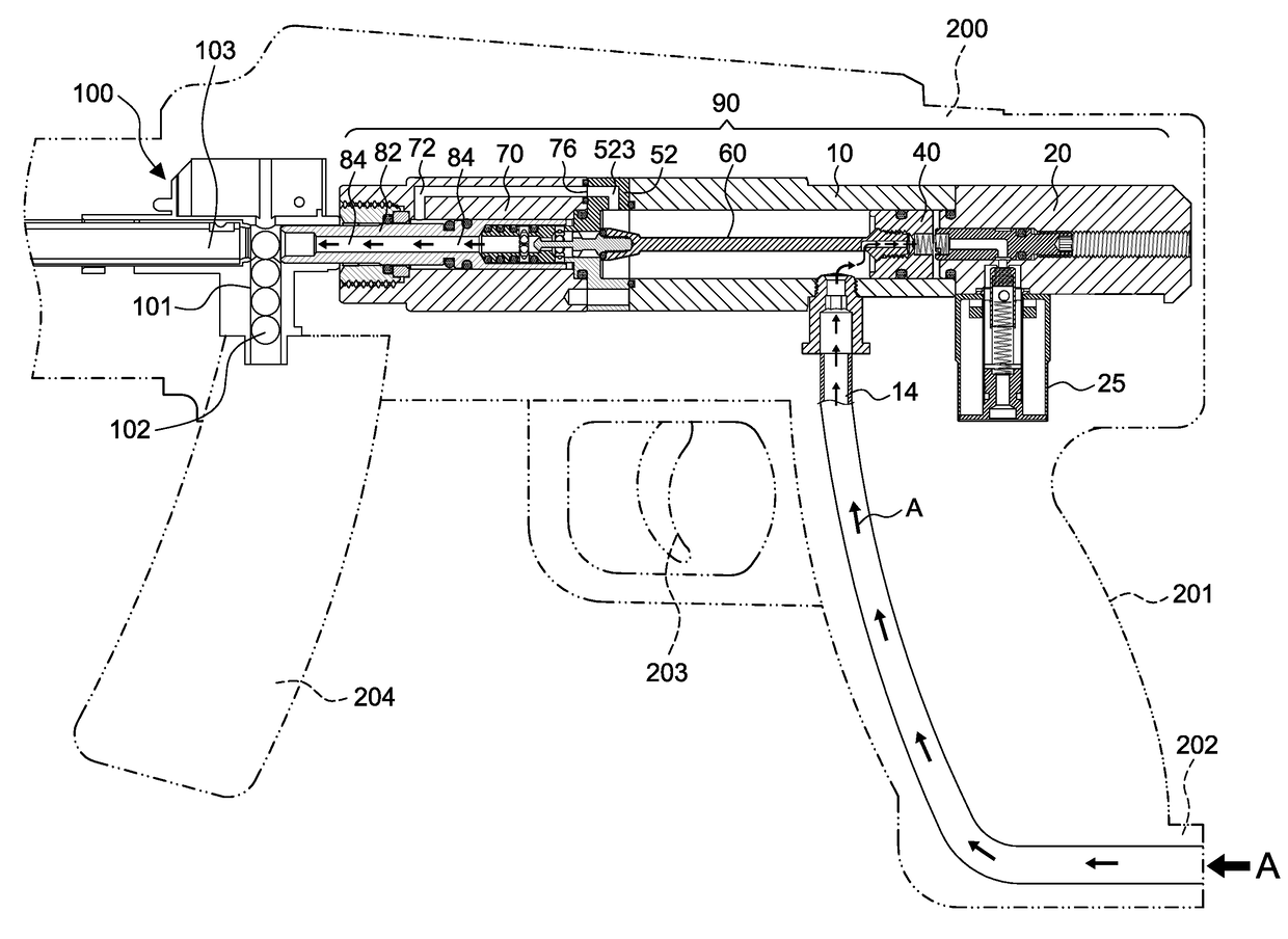
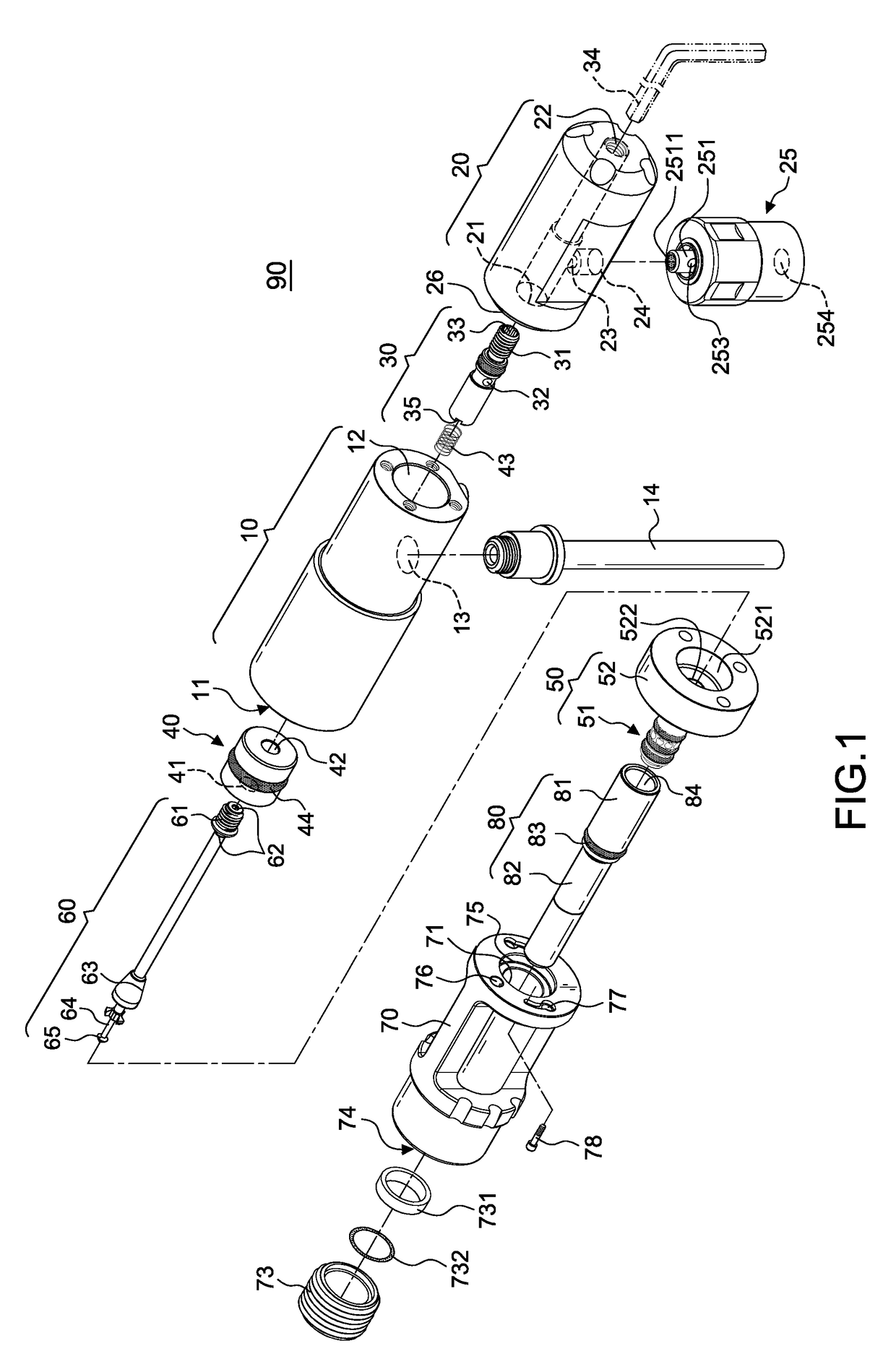
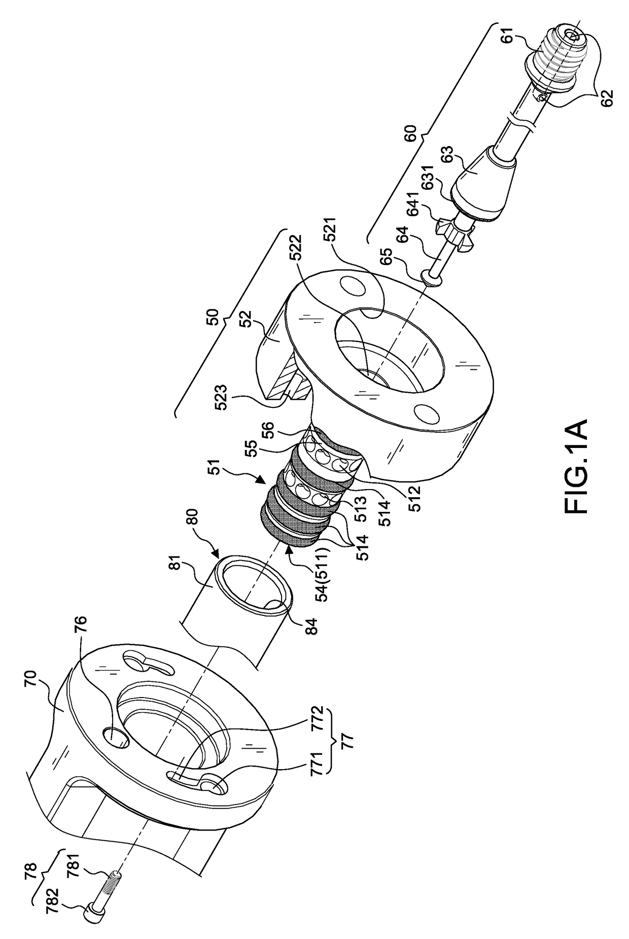
[0052]A preferred embodiment is illustrated in FIGS. 1-9, among which FIG. 9 is a practical application view of the present invention applied to a Ball Bearing gun (BB gun). Referring to FIGS. 1-3C, the present invention, a pneumatic firing device 90, includes a hollow cylinder 10, a rear section 20, a solenoid valve 25, an adjusting element 30, a piston 40, an airflow guiding element 50, a moving rod 60, a front section 70, a delivery tube 80, and a positioning element 73.

[0053]The hollow cylinder 10 includes a first opening 11 arranged at an end thereof, a second opening 12 arranged at the other end thereof, and a first entry hole 13 arranged at the bottom thereof for connecting an external air supply tube 14.

[0054]The rear section 20 has a front end engaging the second opening 12, a first hole 21 arranged at a front part thereof, a screw hole 22 arranged at a rear part thereof connecting to the first hole 21, and a pressure release vent 23 arranged at the bottom thereof connectin...


PUM


Abstract

A pneumatic firing device includes a rear section engaging a cylinder, a solenoid valve engaging the rear section from under, an adjusting element disposed inside the rear section, a piston disposed inside the cylinder to form a first chamber and a second chamber, an airflow guiding element engaging the cylinder at a front thereof, a moving rod having a tail end engaging the piston and a front end stretching through the cylinder into the airflow guiding element for operation control of the airflow guiding element, and a front section engaging a front of the airflow guiding element and having a plurality of passage to displace the delivery tube through a hole thereof. The solenoid valve holds control of the operation of a pressure release channel to change the pressure difference between the first and second chamber, making the pressured air entering a first passage from a first guiding hole of the airflow guiding element, pushing the delivery tube to a firing position, flowing into a second passage from a second guiding hole, and then firing a pellet with strong airflow.

Description

BACKGROUND OF THE INVENTION[0001]1. Field of the Invention[0002]The present invention relates to a pneumatic firing device, particularly to one that fires pellets by airflows produced from the operation of a pressure release channel and that is especially suitable for application to Ball Bearing guns, also known as BB guns.[0003]2. Description of the Related Art[0004]Nowadays people like to play war games like paintball and survival games with air gun including BB guns that are highly intense for stress relief, especially those living in cities.[0005]Both BB guns and paintball guns fire the pellets by pressured air, mechanically or electronically. A mechanical firing has a trigger controlling the air passage within the device to fire, each pulled for one shot, but a user of mechanical guns cannot pull the trigger fast enough for rapid fires. An electronic firing has a trigger controlling the operation of a solenoid valve in the device to fire, and it is able to conduct rapid fire.[0...

Claims


Application Information

Patent Timeline
Patent Type & Authority Applications(United States)
IPC IPC(8): F41B11/723F41B11/642
CPCF41B11/642F41B11/723F41B11/721
Inventor SHEN, LIANG-CHI
Owner SHEN LIANG CHI
Why Eureka
Try Eureka