Technique for transmitting and receiving system time information in broadcasting system

a technology of transmitting system and receiving system, which is applied in the direction of broadcast/distribution synchronisation by plural systems, digital transmission, data switching networks, etc., can solve the problem that the detailed method of providing a reference time for synchronization has not yet been proposed

Active Publication Date: 2017-06-08
SAMSUNG ELECTRONICS CO LTD
View PDF16 Cites 19 Cited by
  • Summary
  • Abstract
  • Description
  • Claims
  • Application Information

AI Technical Summary

Benefits of technology

[0014]A client may play back a media content at a planed point in time, irrespective of the type of network that transmits the media content. Consequentially, all clients can play back the media content at a point in time that is synchronized with a system time.
[0015]The client use absolute time information that is transmitted through an L1 signaling or an L2 signaling, and thus, may be synchronized with the absolute time of the system without an error associated with a transmission delay.

Problems solved by technology

However, a detailed method of providing a reference time to be used for the synchronization has not yet been proposed.

Method used


Image

  • Technique for transmitting and receiving system time information in broadcasting system
  • Technique for transmitting and receiving system time information in broadcasting system
  • Technique for transmitting and receiving system time information in broadcasting system

Examples


first embodiment

[0018]FIG. 3 is a diagram illustrating a frame structure associated with an L1 data pipe according to the present disclosure;

[0019]FIGS. 4A and 4B are diagrams illustrating a structure of an L1 frame according to the first embodiment of the present disclosure;

second embodiment

[0020]FIG. 5 is a diagram illustrating a structure of an L2 protocol according to the present disclosure;

[0021]FIG. 6 is a diagram illustrating a data transmission method of a system according to embodiments of the present disclosure;

[0022]FIG. 7 is a diagram illustrating a configuration of a system device according to embodiments of the present disclosure;

[0023]FIG. 8 is a diagram illustrating a data receiving method of a client according to embodiments of the present disclosure;

[0024]FIG. 9 is a diagram illustrating a configuration of a client device according to embodiments of the present disclosure;

[0025]FIG. 10 is a diagram illustrating a method that a client uses for the synchronization of heterogeneous network contents according to embodiments of the present disclosure; and

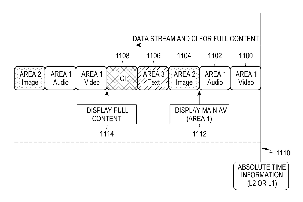
[0026]FIG. 11 is a diagram illustrating a mechanism that synchronizes a plurality of service components received from a heterogeneous network, and plays back the same according to embodiments of the present...


PUM


Abstract

The present disclosure provides a data transmission method of a system in an IP based broadcasting network, the data transmission method comprising the steps of: generating an MPEG media transport protocol (MMTP) packet using a media processing unit (MPU) for a service; generating an IP packet using the MMTP packet; generating a layer 2 (L2) packet using the IP packet and generating a layer 1 (L1) packet stream using the L2 packet; and transmitting the L1 packet stream, wherein absolute time information of the system is included in one of a transmission frame of the L1 packet stream and the L2 packet.

Description

CROSS-REFERENCE TO RELATED APPLICATION(S)[0001]This application is a National Phase Entry of PCT International Application No. PCT / KR2015 / 006383, which was filed on Jun. 23, 2015, and claims a priority to Korean Patent Application No. 10-2014-0077730, which was filed on Jun. 24, 2014, the contents of which are incorporated herein by reference.TECHNICAL FIELD[0002]The present disclosure relates to a method of transmitting and receiving system time information in a broadcasting system, and more particularly, to a method and apparatus for transmitting and receiving data including the system time information.BACKGROUND ART[0003]Recently, an Internet protocol (IP)-based broadcasting communication system that combines communication through a broadband network and communication through a radio frequency (RF), has been designed and established.[0004]As an IP broadcasting network has been introduced, a system clock that was conventionally utilized for moving pictures expert group (MPEG) 2 tr...

Claims


Application Information

Patent Timeline
Patent Type & Authority Applications(United States)
IPC IPC(8): H04N21/2381H04N21/643H04N21/2368H04N21/434H04L29/06H04L12/24
CPCH04N21/2381H04L29/06027H04N21/64322H04N21/2368H04N21/4347H04L41/0246H04N21/234H04N21/242H04H20/18H04H60/40H04H60/82H04L65/611H04L65/70H04N21/23605H04N21/2343H04L65/1101
Inventor HWANG, SUNG-OHYANG, HYUN-KOOPARK, KYUNG-MOLIM, YOUNG-KWONKEUM, JI-EUN
Owner SAMSUNG ELECTRONICS CO LTD
Why Eureka
Try Eureka