Measuring robot performance

a robot and performance measurement technology, applied in the field of measuring robot performance, can solve the problems of unnecessarily disrupting the tissue of a patient, unable to reach the desired position, and overshooting the desired configuration of the arm,

Active Publication Date: 2017-06-15
CMR SURGICAL LTD
View PDF0 Cites 26 Cited by
  • Summary
  • Abstract
  • Description
  • Claims
  • Application Information

AI Technical Summary

Benefits of technology

[0012]Once the loss in the gearbox has been estimated as described above, the control system may cause the arm to move at a desired rate by determining a power to be applied to the motor. That power may be determined in dependence on the estimated loss. The power may be determined so as to overcome that loss.

Problems solved by technology

However, the arm may overshoot the desired configuration and have to be brought back, or fail to reach the desired position by the required time.
Failures of the first type are especially important when the arm is part of a surgical robot because they may result in tissue of a patient being unnecessarily disrupted.
Another form of difficulty arises when the torque sensor is being used to sense the torque being applied on the joint 1 by an external force, such as gravity, at the same time as the distal limb is being driven by the motor 5.
Without knowing the performance of the gearbox 7 it is difficult to estimate the external torque.
This may be problematic if the control strategy of the arm is dependent on an estimate of the externally applied torque.
However, this adds weight, cost and complexity to the arm.
Another alternative would be to remove the gearbox from the arm and measure its losses, but that is time-consuming and can only be undertaken when the arm is not in use.

Method used


Image

  • Measuring robot performance
  • Measuring robot performance
  • Measuring robot performance

Examples


Embodiment Construction

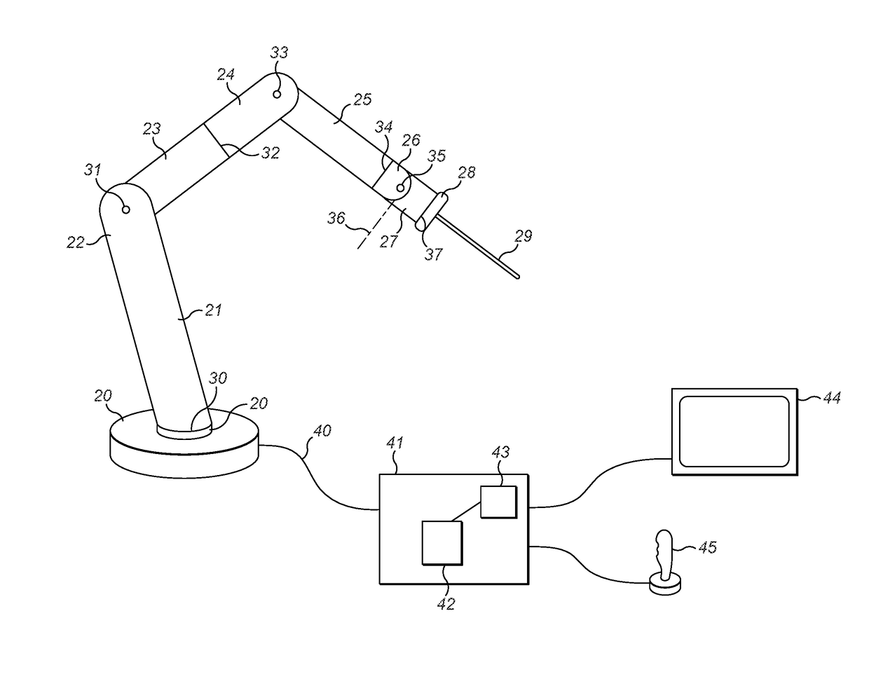
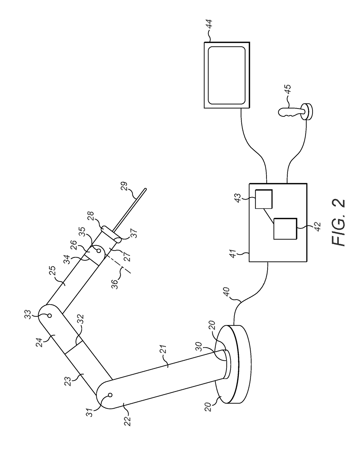
[0018]In the arrangement of FIG. 2 the robot arm includes a series of rigid members 20-28 which are connected in series, with joints 30-37 between successive pairs of members. As an example, members 24, 25 are interconnected by a revolute joint 33. Joint 33 is shown in more detail in FIG. 3. Relative motion of members 24, 25 at the joint 33 can be driven by motor 51 acting through gearbox 53. A torque sensor 59 measures the torque applied at the joint, and a position encoder 60 senses the positional configuration of the joint. A control unit 41 (FIG. 2) receives signals from the torque sensor and the position encoder and generates drive signals to the motor 51. The control system is configured so as to be capable of driving the arm in such a way as to allow it to estimate the mechanical losses between the motor 51 and joint 33. On way in which this can be done is by measuring the actual motion of the arm about the joint when a known power is applied from the motor. If the joint is d...


PUM


Abstract

A robot comprising: a base; an articulated arm extending distally of the base and including two arm members coupled by a joint; a motor; a gearbox having an input shaft coupled to an output of the motor and an output shaft configured to drive relative motion of the arm members about the joint; a position sensor configured to sense relative position of the arm members about the joint; and a control system coupled to the arm configured to drive the motor, the control system being arranged to perform a calibration operation to estimate torque loss in the gearbox by the steps of (i) estimating the inertia of the portion of the arm distal of the joint for motion about the joint; (ii) applying a determined drive power to the motor; (iii) receiving from the position sensor position data indicating the motion of the arm in response to the applied drive power; and (iv) estimating the torque loss in the gearbox in dependence on the estimated inertia, the determined drive power and the position data.

Description

CROSS-REFERENCE TO RELATED APPLICATIONS[0001]This application claims benefit under 35 USC 119 of United Kingdom Application No. 1521815.9, filed Dec. 10, 2015. The contents of this application is hereby incorporated by reference in its entirety.BACKGROUND[0002]This invention relates to characterising the performance of a robot.[0003]A typical robot arm comprises a number of rigid limbs, each of which is connected to the next by an articulation which may, for example, be a revolute joint. A motor or other drive mechanism is provided to drive relative motion of the limbs at each joint.[0004]FIG. 1 shows an example of a drive mechanism at a robot arm articulation. The articulation 1 of FIG. 1 is located between a proximal arm member 2 and a distal arm member 3. The arm members are coupled together by a revolute joint defined by a rotation axis 4. An electric motor 5 is mounted in the proximal arm member 2. The output of the electric motor is a drive shaft 6 which connects to the input ...

Claims


Application Information

Patent Timeline
Patent Type & Authority Applications(United States)
IPC IPC(8): B25J9/16B25J9/10B25J19/02B25J9/12
CPCB25J9/1641B25J9/126B25J9/102Y10S901/09B25J9/1692B25J9/1694B25J19/02B25J17/00G05B2219/39191G05B2219/41359A61B34/70B25J13/085
Inventor HARES, LUKE DAVID RONALD
Owner CMR SURGICAL LTD
Why Eureka
Try Eureka