Current detection circuit

A current detection circuit and circuit technology, applied in the direction of measuring current/voltage, measuring device, measuring electrical variables, etc., can solve difficult integrated circuit applications, prominent cost problems of rectifier bridges and diodes, loss of AC signal amplitude and interference conditions, etc. problem, to achieve the effect of easy low-cost integration, easy and accurate phase identification, and cost reduction

Inactive Publication Date: 2012-11-28
UNIV OF ELECTRONICS SCI & TECH OF CHINA
View PDF6 Cites 11 Cited by
  • Summary
  • Abstract
  • Description
  • Claims
  • Application Information

AI Technical Summary

Problems solved by technology

CN 202217009U discloses a detection circuit. Specifically, through diode rectification, the information of the AC signal to be detected is obtained by converting it into a square wave in phase with the AC signal by means of an optocoupler, but this nonlinear processing method loses information such as AC signal In addition, the use of rectifier bridges and diodes causes cost problems to be more prominent, and it is not easy to apply in integrated circuits

Method used


Image

  • Current detection circuit
  • Current detection circuit
  • Current detection circuit

Examples


Embodiment 1

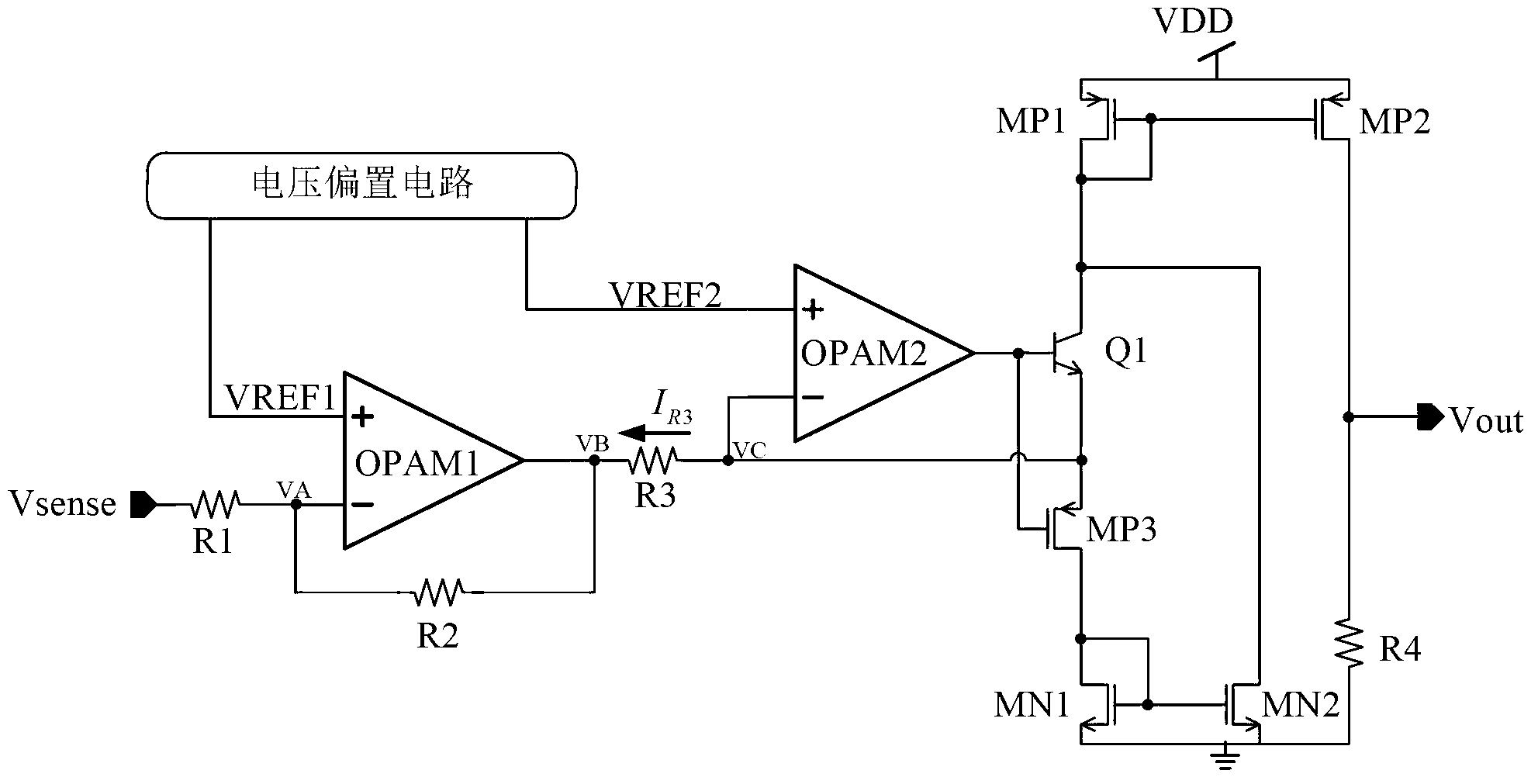
[0016] Embodiment one: if figure 2 As shown, the current detection circuit specifically includes: a voltage bias circuit, a first amplifier OPAM1, a second amplifier OPAM2, a first resistor R1, a second resistor R2, a third resistor R3, a fourth resistor R4, a first NMOS transistor MN1, The second NMOS transistor MN2, the first PMOS transistor MP1, the second PMOS transistor MP2, the third PMOS transistor MP3 and a switch element, wherein the voltage bias circuit provides the amplifier OPAM1 and the amplifier OPAM2 with the first reference voltage VREF1 and The second reference voltage VREF2 is respectively input to the positive input terminals of the amplifiers OPAM1 and OPAM2, the first terminal of the first resistor R1 is used as the input terminal of the current detection circuit for inputting the signal Vsense to be detected, and the second terminal of the resistor R1 Connect the negative input terminal of the amplifier OPAM1 and the first terminal of the resistor R2, th...

Embodiment 2

[0051] Embodiment two, such as Figure 4 As shown, the difference from Embodiment 1 is that the second amplifier OPAM2 at this time uses MOS transistors as the differential pair of transistors, and the switching element uses NMOS transistor MN0, wherein the gate of MN0 is used as the first end of the switching element, and the source is used as the first end of the switching element. The second end and the drain of the switch element are used as the third end of the switch element. Here, using the switching element of the MOS tube will reduce the distortion of the detection signal and improve the accuracy of the current detection. The principle and working process of the second embodiment are the same as those of the first embodiment, and will not be described in detail.

Embodiment 3

[0052] Embodiment three, such as Figure 5 As shown, an NMOS transistor MN3 is connected in series between the output terminal of the second mirror circuit and the input terminal of the first mirror circuit, and its gate can be connected to the third reference voltage VREF3. This structure will reduce the mirror deviation of the second mirror circuit and further improve the accuracy of current detection, which can also be applied to the second embodiment. The principle and working process of the third embodiment are the same as those of the first embodiment, and will not be described in detail.

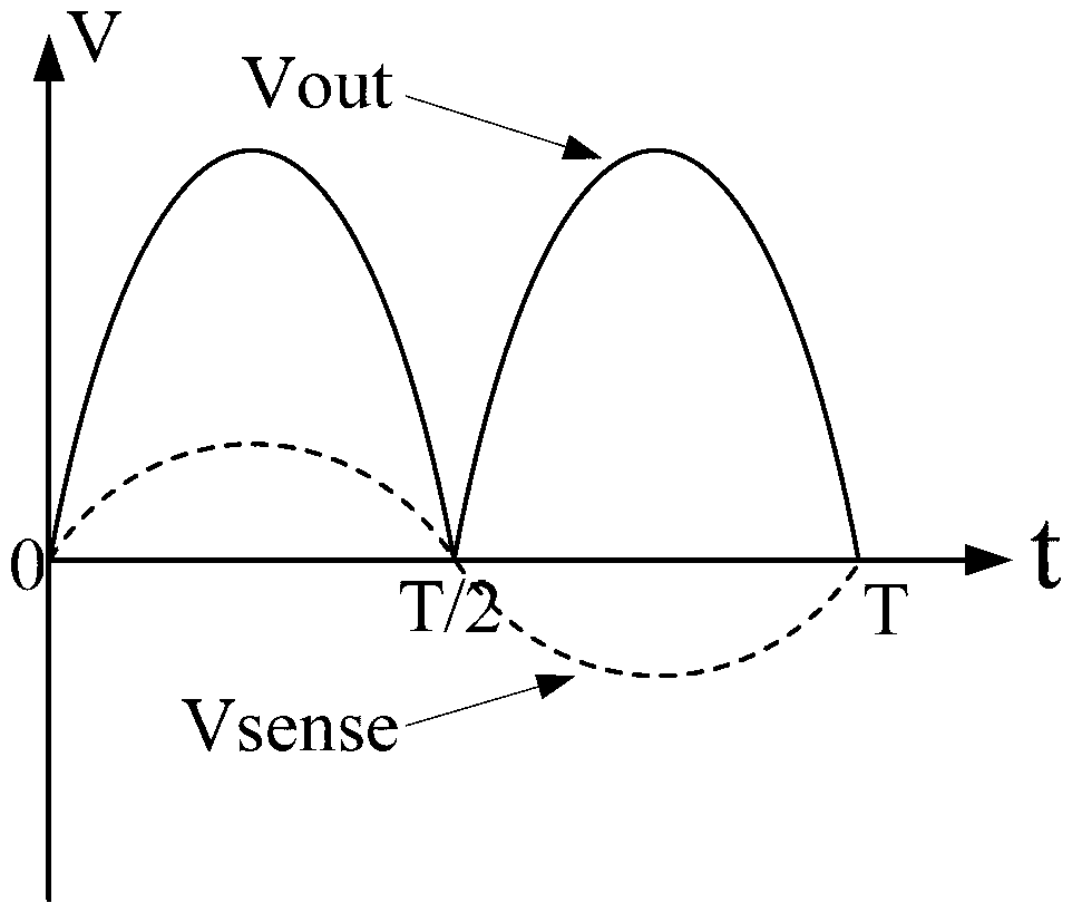
[0053] The current detection circuit with full-phase current detection function proposed by the present invention uses the amplifier to judge the phase, and the mirror image process of the current mirror realizes the direction change processing of the current, and completes the following steps: image 3 The rectified linearized amplification function is shown. The current detection ...


PUM


Abstract

The invention discloses a current detection circuit, which comprises a voltage bias circuit, a first amplifier, a second amplifier, a first resistor, a second resistor, a third resistor, a fourth resistor, a first N-channel metal oxide semiconductor (NMOS) tube, a second NMOS tube, a first P-channel metal oxide semiconductor (PMOS) tube, a second PMOS tube, a third PMOS tube and a switch component. In the current detection circuit, a full-phase current sampling signal is subjected to level shift amplification by a level shift operational amplifier consisting of the first amplifier, the first resistor and the second resistor, so that a current phase discrimination circuit consisting of the second amplifier, the third resistor, the switch component and the third PMOS tube can discriminate phase correctly; and the current phase discrimination circuit outputs a control signal, controls the switch component to adjust the flowing direction of signal current and replaces the traditional rectifier bridge or the diode to finish the rectification function, so that the full-phase current detection function of a power supply circuit of a single power supply without the rectifier bridge or the diode is realized.

Description

technical field [0001] The invention belongs to the technical field of integrated circuits, and in particular relates to the design of a current detection circuit for realizing full-phase current detection. Background technique [0002] Current detection plays an important role in current control, and current detection is divided into resistance detection and current transformer detection. In low and medium power applications, the use of coils in the current transformer detection circuit brings problems such as high circuit cost and poor consistency of batch products. [0003] figure 1 A schematic diagram of the structure of the existing single power supply circuit to realize AC current detection is given. The existing idea is usually to use a rectifier bridge or diode to rectify the detection signal, convert it into DC, and indirectly realize the full-phase current detection. CN 202217009U discloses a detection circuit. Specifically, through diode rectification, the infor...

Claims


Application Information

Patent Timeline
Patent Type & Authority Applications(China)
IPC IPC(8): G01R19/00
Inventor 周泽坤吴传奎邱实王鑫石跃明鑫张波
Owner UNIV OF ELECTRONICS SCI & TECH OF CHINA
Why Eureka
Try Eureka