Electronic stability control system for vehicle

a technology of electronic stability control and vehicle, applied in the direction of braking system, electric device, braking components, etc., can solve the problems of increasing electric consumption, affecting vehicle stability, and affecting vehicle stability, so as to reduce the effect of electrical efficiency and improve vehicle stability

Active Publication Date: 2017-06-15
NTN CORP
View PDF4 Cites 17 Cited by
  • Summary
  • Abstract
  • Description
  • Claims
  • Application Information

AI Technical Summary

Benefits of technology

[0039]When the stability determination module 20 determines that the vehicle is in the oversteer state or in the understeer state, the braking/driving force control module 21 may apply a braking force and a driving force having the same absolute value to respective ones of the pair of left and right drive wheels, Compared to the case where a braking force is applied to only one wheel, the absolute value of a braking/driving force per wheel can be reduced, and therefore, the tire load rate can be made uniform, resulting in an improvement in vehicle stability.
[0040]The braking/driving force control module 21 may apply the braking force by a regenerative torque of the motor 3 associated wit...

Problems solved by technology

While an electronic stability control system which applies a braking force to a wheel to be controlled using a brake can generate a great yaw moment, such an electronic stability control system has a problem that a deceleration is caused in a vehicle body during the operation of the electronic stability control system, which causes the driver feel uncomfortable.
Furthermore, when a friction brake is used to generate a braking force, the kinetic energy of a vehicle dissipates as thermal energy, leading to a decrease in electrical efficiency,...

Method used


Image

  • Electronic stability control system for vehicle
  • Electronic stability control system for vehicle
  • Electronic stability control system for vehicle

Examples


Embodiment Construction

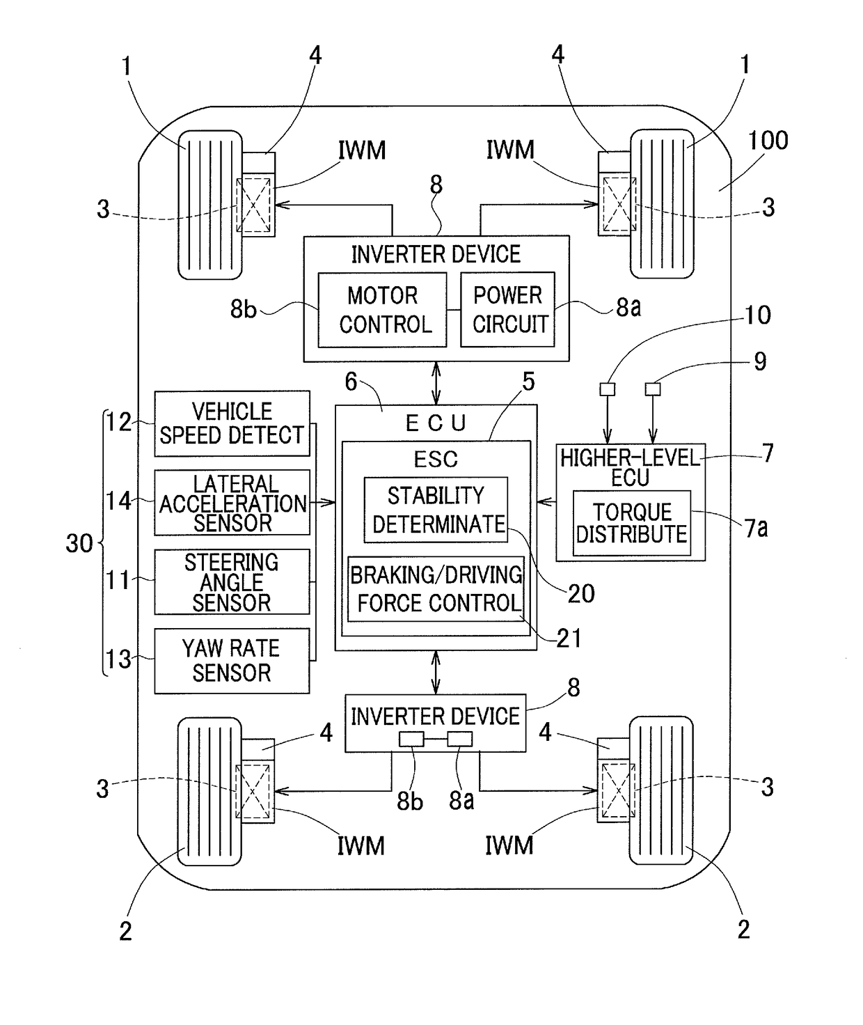
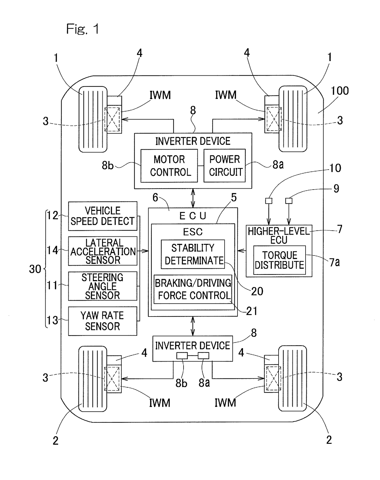
[0053]A vehicle electronic stability control system according to a first embodiment of the present invention will be described with reference to FIGS. 1 to 5.

[0054]FIG. 1 is a plan view schematically showing a system configuration of the vehicle electronic stability control system 5. The electronic stability control system 5 is for preventing. a vehicle from skidding. In this embodiment, a vehicle 100 is a four-wheel drive automobile which includes the electronic stability control system 5. The vehicle 100 includes a pair of left and right front wheels 1, 1 and a pair of left and right rear wheels 2, 2. The wheels are individually driven by the respective motors 3.

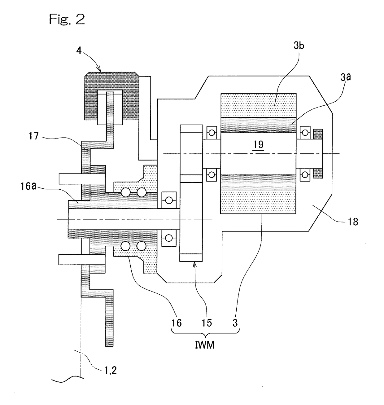
[0055]Each motor 3 includes an in-wheel motor drive device IWM described below. The pair of left and right front wheels 1, 1 can be turned by a turning mechanism (not shown), and are steered by a steering wheel through the turning mechanism. This vehicle includes friction brakes 4 which apply frictional braking forces to t...


PUM


Abstract

A vehicle electronic stability control system allows a vehicle to have improved movement performance and limit performance without causing a driver to feel uncomfortable, by actuating electronic stability control from a state where a lateral slip is relatively less likely to occur. The system prevents skidding of a vehicle including motors which individually drive a pair of left and right drive wheels. A stability determination module obtains information indicating vehicle behavior from a sensor, and determines whether or not the vehicle is in an unstable or less stable state, on the basis of the information. A braking/driving force control module which, when the stability determination module determines that the vehicle is in the unstable or less stable state, applies a braking force to one of the drive wheels, and simultaneously applies a driving force to the motor for the other drive wheel.

Description

CROSS REFERENCE TO THE RELATED APPLICATION[0001]This application is a continuation application under 35 U.S.C. §111(a), of international application No. PCT / JP20151074183, filed Aug. 27, 2015, which claims Convention priority to Japanese patent application No. 2014-177107, filed Sep. 1, 2014, the entire disclosure of which is herein incorporated by reference as a part of this application.BACKGROUND OF THE INVENTION[0002]Field of the Invention[0003]The present invention relates to an electronic stability control system for vehicle, which improves cornering performance and stabilizes vehicle behavior in a cornering limit region. Particularly, the present invention relates to an electronic stability control system for an in-wheel motor vehicle.[0004]Description of Related Art[0005]Among conventionally known techniques for controlling the orientation of a vehicle is a control device for preventing a skid (electronic stability control, abbreviated to ESC). The electronic stability contro...

Claims


Application Information

Patent Timeline
IPC IPC(8): B60W30/02B60W10/184B60W10/08B60L15/20B60L7/24B60K1/02B60L7/10B60L7/26B60K7/00B60T8/1755
CPCB60W30/02B60Y2300/89B60W10/184B60W10/08B60T8/1755B60L7/24B60K1/02B60L7/10B60L7/26B60L15/20B60T2270/303B60W30/045B60Y2300/02B60Y2300/045B60Y2300/60B60W2520/10B60W2520/125B60W2520/14B60W2510/207B60K7/0007Y02T10/72B60L3/10B60T8/17
Inventor SUGAI, TOMOHIRO
Owner NTN CORP
Why Eureka
Try Eureka