Absolute measuring length measuring system and method for its operation

Active Publication Date: 2017-06-15
BALLUFF
View PDF2 Cites 1 Cited by
  • Summary
  • Abstract
  • Description
  • Claims
  • Application Information

AI Technical Summary

Benefits of technology

[0007]The object of the invention is to state a length or position measuring system related here, and a method for its use, with which the number of sensors required to evaluate the PR

Problems solved by technology

Thus, the length of a PRC sensor array formed from the sensors for evaluating the

Method used


Image

  • Absolute measuring length measuring system and method for its operation
  • Absolute measuring length measuring system and method for its operation
  • Absolute measuring length measuring system and method for its operation

Examples


Example

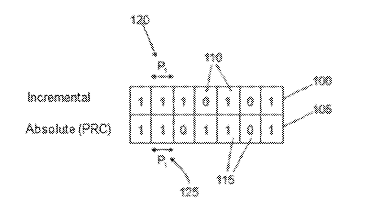
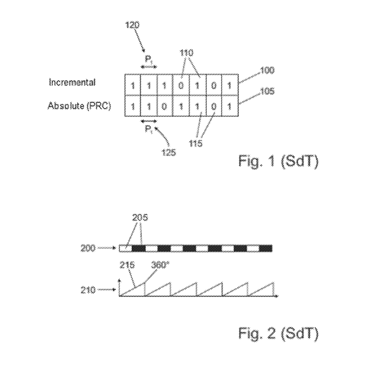
[0027]In FIG. 1, a conventional linear measuring gauge of a magnetic tape length measuring system (BML) with an incremental track 100 and a pseudo-random coded (PRC) absolute track 105 connected fixedly or immovably to the incremental track 100 is schematically depicted. The incremental track 100 has varyingly binarily coded poles 110 and the absolute track 105 has similarly binarily coded poles 115. Both the absolute track 105 and the incremental track 100 have a respectively concordant pole width ‘P1’120, 125.

[0028]Along with the conventional application scenarios with a substantially linear measuring section, such a measuring gauge 100, 105 can also be arranged on the circumference of a shaft, e.g. a drive shaft of a wind turbine or similar which is not shown. The BML thus serves to monitor or maintain the wind turbine if the position of the drive shaft has to be precisely detected.

[0029]The angle detected by the incremental sensor changes in each pole or pole pair 205, as is kno...


PUM


Abstract

In a length or position measuring system which has an at least locally substantially linear measuring gauge and at least one sensor able to be moved relative to the measuring gauge wherein the measuring gauge includes an incremental track and at least one absolute track and wherein the incremental track and the at least one absolute track have pole pairs arranged in the longitudinal direction of the measuring gauge, it is provided in particular that at least one pole pair of the absolute track is phase-shifted relative to a corresponding pole pair of the incremental track.

Description

CROSS REFERENCE TO RELATED APPLICATIONS[0001]Applicant claims priority under 35 U.S.C. §119 of German Application No. 10 2015 121 474.1 filed Dec. 9, 2015, the disclosure of which is incorporated by reference.BACKGROUND OF THE INVENTION1. Field of the Invention[0002]The invention relates to an absolute length measuring system or position measuring system having a preferably magnetically coded measuring gauge having an incremental track and at least one absolute track, and to a method for operating such a length or position measuring system, according to the type of the respective independent claims.2. Description of the Related ArtIncremental Measuring Systems[0003]Magnetic strip length measuring systems have become known in the field of measuring technology, in which a sensor head is moved across a measuring gauge (incremental track) that is periodically magnetized with changing polarity. Ideally, a sine-shaped and cosine-shaped sensor signal is generated in the sensor head or magn...

Claims


Application Information

Patent Timeline
IPC IPC(8): G01D5/249
CPCG01D5/2497G01D5/2454G01D5/2455G01D5/2495
Inventor BURKHARDT, THOMAS
Owner BALLUFF
Why Eureka
Try Eureka