
Narrow directional microphone

a microphone and directional technology, applied in the direction of microphones, microphone structural associations, electrical equipment, etc., can solve the problem of difficult to suppress wind nois

Inactive Publication Date: 2017-06-15
AUDIO-TECHNICA
View PDF4 Cites 4 Cited by
  • Summary
  • Abstract
  • Description
  • Claims
  • Application Information

AI Technical Summary

Benefits of technology

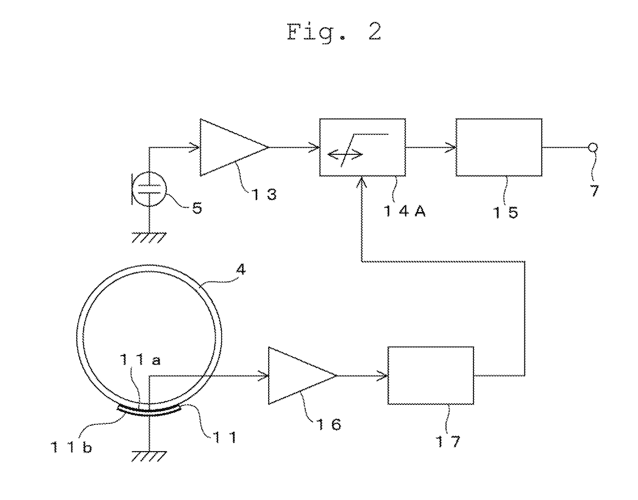
The present invention is about a narrow directional microphone that can suppress wind and vibration noise caused by the microphone's own acoustic tube. The invention uses an attenuation circuit that can reduce the entire band of audio signals based on the detection output. This results in a more accurate recording of sounds in the narrow directional microphone.

Problems solved by technology

By the way, in a case of the narrow directional microphone using the acoustic tube described above, a specific wind noise is also generated in addition to the vibration noise, and it is difficult to suppress the wind noise by the means for decreasing a vibration noise, disclosed in the patent document No. 4000217 B2.

Method used


Image

  • Narrow directional microphone
  • Narrow directional microphone
  • Narrow directional microphone

Examples


Embodiment Construction

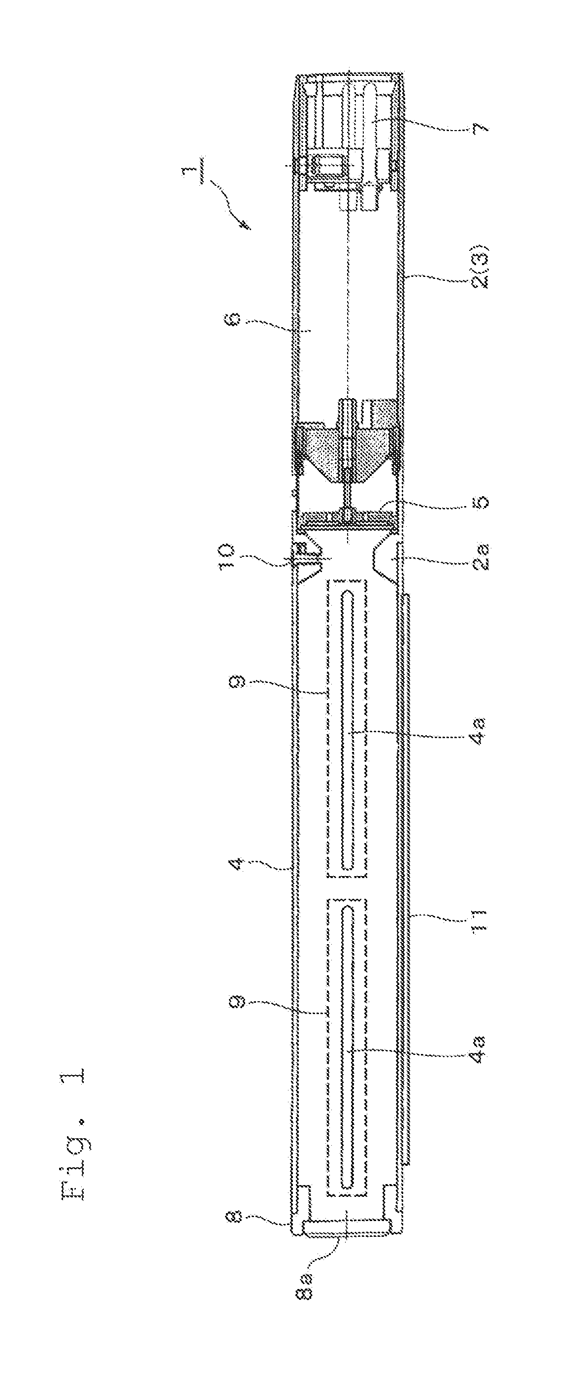
[0024]A narrow directional microphone according to the present invention will be described on the basis of embodiments illustrated in the drawings. FIG. 1 illustrates a first embodiment of a narrow directional microphone. An outer wall of a narrow directional microphone 1 illustrated in FIG. 1 is formed of a unit case 2 made of aluminum material, for example, and having an outer surface functioning as a grip 3, and an acoustic tube 4 formed of resin material in a tubular shape and attached to a front end portion of the unit case 2.

[0025]That is, the unit case 2 and the acoustic tube 4 have nearly the same outer diameter dimension and are coaxially combined, so that the entire body forms a long cylindrical shape.

[0026]A microphone unit 5 is attached to a front end portion in the unit case 2, and therefore the microphone unit 5 is arranged in an inner bottom portion of the acoustic tube 4 attached to the unit case 2.

[0027]The microphone unit 5 is formed of a condenser microphone unit....


PUM


Abstract

A narrow directional microphone includes a unit case having a front end portion to which a microphone unit is mounted, and a side surface functioning as a grip, an acoustic tube formed of resin material in a tubular shape, covering the microphone unit, and attached to the front end portion of the unit case such that the microphone unit is positioned to an inner bottom portion of the acoustic tube, a piezoelectric film that is arranged in at least one part of the acoustic tube, and that generates a detection output based on a mechanical deformation of the acoustic tube, and an output signal processing unit including an attenuation circuit that attenuates an audio signal from the microphone unit with the detection output from the piezoelectric film and sends the attenuated audio signal to a signal output unit.

Description

BACKGROUND OF THE INVENTIONField of the Invention[0001]The present invention relates to a narrow directional microphone using an acoustic tube, and especially relates to a narrow directional microphone that can decrease a wind noise and a vibration noise.Description of the Related Art[0002]A narrow directional microphone using a long and narrow acoustic tube and having a microphone unit arranged in an inner bottom portion of the acoustic tube has been known, and this narrow directional microphone has high sensitivity characteristics for a sound wave entering from a front end portion in an axial direction of the acoustic tube.[0003]That is, in the acoustic tube, the front end portion thereof is open, for example, slit-like sound wave introduction ports are formed in a side surface, and an acoustic resistance material is stuck to the sound wave introduction port in the side surface. With this configuration, among sound waves from directions other than the axial direction of the acoust...

Claims


Application Information

Patent Timeline
Patent Type & Authority Applications(United States)
IPC IPC(8): H04R29/00H04R3/04H04R1/04
CPCH04R29/004H04R2410/07H04R3/04H04R1/04
Inventor AKINO, HIROSHI
Owner AUDIO-TECHNICA
Learn More