Method of locating center position and axial direction of distal locking hole of intramedullary nail

a technology of locking hole and center position, applied in the field of methods of locating distal locking hole of intramedullary nail, can solve the problems of ineffective process, high radiation dose of x-ray image, and inability to quickly and precisely align the nail, so as to reduce the radiation dose of x-ray

Active Publication Date: 2017-06-22
NAT CENT UNIV
View PDF2 Cites 1 Cited by
  • Summary
  • Abstract
  • Description
  • Claims
  • Application Information

AI Technical Summary

Benefits of technology

[0008]It is an objective of the present invention to provide a method of locating a distal locking hole of an intramedullary nail to achieve quick and precise alignment, reduce the number of required X-ray images, and thereby reduce the radiation dose of X-ray which medical persons and the patient might otherwise be exposed to.
[0012]In conclusion, a method of locating a distal locking hole of an intramedullary nail is effective in not only locating a distal locking hole by using just one X-ray image quickly and precisely but also reducing the number of required X-ray images to thereby reduce the radiation dose of X-ray which medical persons and the patient might otherwise be exposed to.

Problems solved by technology

But, the X-ray image-taking process is not only time-consuming but also exposes medical persons and the patient to hazardously high level of radiation, not to mention that the process is not effective in drilling the bone at points thereof corresponding in the center positions and axial directions to the distal locking holes of the intramedullary nail, respectively.
Furthermore, an X-ray image device, namely C-arm, has to move slowly in order to take several anterior-posterior and lateral X-ray images; as a result, it is time-consuming to drill the bone at points thereof corresponding in the center positions and axial directions to the distal locking holes of an intramedullary nail in a fractured bone, respectively.
Furthermore, quick and precise alignment is impossible, because each X-ray image shows the distal locking holes of the intramedullary nail in just one direction which is not enough for the surgeon to quickly and precisely align the locking holes, even though several anterior-posterior and lateral X-ray images of the intramedullary nail are taken.

Method used


Image

  • Method of locating center position and axial direction of distal locking hole of intramedullary nail
  • Method of locating center position and axial direction of distal locking hole of intramedullary nail
  • Method of locating center position and axial direction of distal locking hole of intramedullary nail

Examples


Embodiment Construction

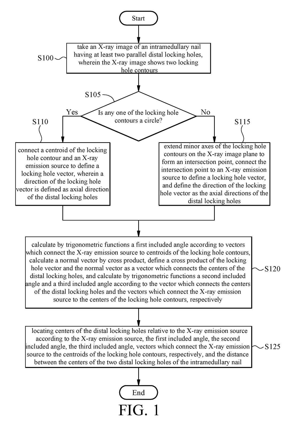
[0020]Referring to FIG. 1, it is shown a first flowchart of a method of locating distal locking holes of an intramedullary nail according to the present invention. With the method, the distal locking holes of an intramedullary nail can be quickly located in terms of axial directions and positions. The method works in conjunction with a processor and is described below.

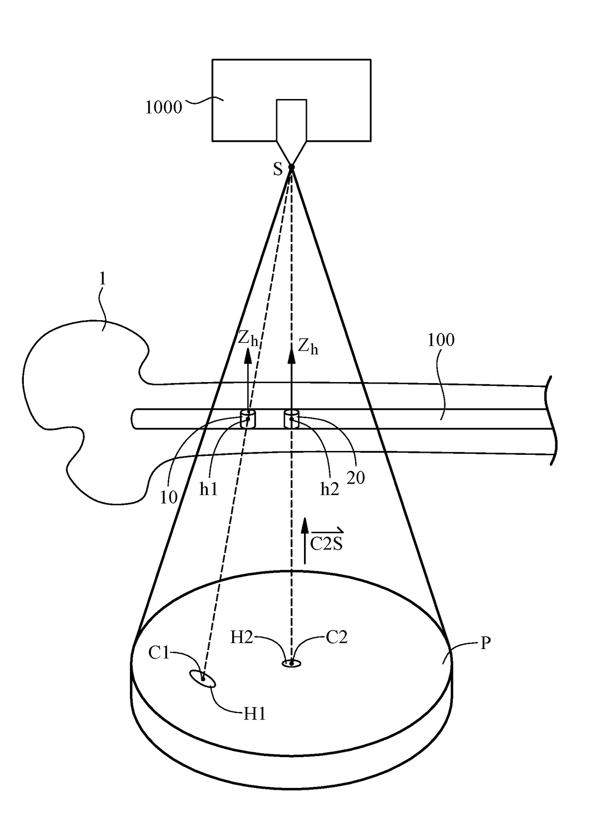
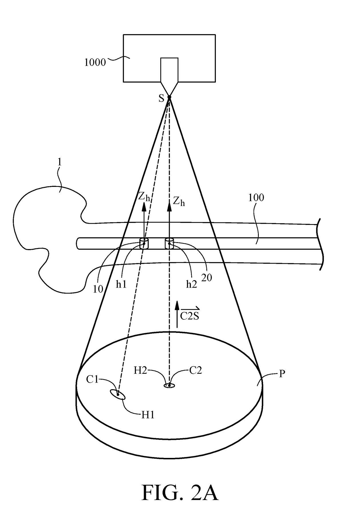
[0021]In step S100 of the method, an intramedullary nail 100 with at least two parallel distal locking holes is implanted into a bone 1. An X-ray image-taking device 1000 takes an X-ray image P of the bone 1, and thus the X-ray image P shows the contours of the two distal locking holes. Referring to FIG. 2A and FIG. 2B, for illustrative sake, the schematic views show the bone 1 rather than the whole human body. The two parallel distal locking holes are defined with first locking hole 10 and second locking hole 20, respectively. Referring to FIG. 2A and FIG. 2B, the contour of the two distal locking holes shown in the X...


PUM


Abstract

A method of locating locking holes of an intramedullary nail includes taking an X-ray image of an intramedullary nail having two locking holes; connecting centroids of the locking hole contours and an X-ray source to define locking hole vectors and axial directions of the locking holes; calculating a first included angle and normal vector perpendicular to vectors connecting the X-ray source and the locking hole contour centroids; defining a cross product of the locking hole vector and the normal vector as a vector connecting centers of the locking holes, and calculating second and third included angles with the vector connecting the locking hole centers and the vectors connecting the X-ray source to the locking hole contour centroids; and locating the locking holes according to the first, second and third included angles, vectors connecting the X-ray source to the locking hole contour centroids, and a distance between the locking holes.

Description

CROSS-REFERENCE TO RELATED APPLICATION[0001]This non-provisional application claims priority under 35 U.S.C. §119(a) on Patent Application No(s).104142377 filed in Taiwan, R.O.C. on Dec. 16, 2015, the entire contents of which are hereby incorporated by reference.FIELD OF THE INVENTION[0002]The present invention relates to methods of locating distal locking holes of an intramedullary nail and, more particularly, to a method of locating distal locking holes of an intramedullary nail by using just one X-ray image.BACKGROUND OF THE INVENTION[0003]Treating a long bone fracture entails implanting an intramedullary nail into the medullary cavity of the bone, drilling the bone at points thereof corresponding in the center positions and axial directions to the distal locking holes of the intramedullary nail, respectively, and driving a locking screw into each drilled hole in the bone and a corresponding one of the distal locking holes so that the bone and the intramedullary nail can be fixed...

Claims


Application Information

Patent Timeline
Patent Type & Authority Applications(United States)
IPC IPC(8): A61B17/17
CPCA61B17/1725A61B17/1703
Inventor TSENG, CHING-SHIOWHSU, WEI-ENYU, CHING-HSIAO
Owner NAT CENT UNIV
Why Eureka
Try Eureka