Device for cleaning a medical vacuum pump

a vacuum pump and vacuum technology, applied in the direction of machines/engines, mechanical equipment, positive displacement liquid engines, etc., can solve the problems of liquid entering the interior of the appliance, the pump cannot be cleaned, and the protection of filters is often inadequate in practice, so as to reduce the time needed for cleaning

Inactive Publication Date: 2017-06-22
MEDELA HLDG AG
View PDF9 Cites 4 Cited by
  • Summary
  • Abstract
  • Description
  • Claims
  • Application Information

AI Technical Summary

Benefits of technology

[0027]In a simple embodiment, the pump assembly of the medical pump is inactive during the cleaning, i.e. the pump itself does not provide suction. In another embodiment, however, the pump is switched on and sucks the cleaning fluid through the vacuum channel. This has the advantage that the individual elements of the pump are in motion and, therefore, all areas can be thoroughly cleaned.
[0028]The device preferably has cleaning programs in which the suction source and, if appropriate, also the pump to be cleaned are only intermittently in operation. Although the pump to be cleaned then supports the passage of the rinsing agent through the vacuum path, the rinsing agent can nevertheless also remain for some time without moving in the path and exert its action. In a preferred variant, the rinsing agent is sucked into the vacuum path in a first step until the entire vacuum path is wetted. A period in which the rinsing agent acts is left to elapse, without application of underpressure, and then the rinsing agent is sucked out. This procedure can be repeated, or air can be sucked directly through for drying. The cleaning of the outer surface by light, fluids or other means can take place previously, at the same time or subsequently. It preferably takes place at the same time, in order to minimize the time needed for the cleaning.

Problems solved by technology

The interior of the pump, in particular the internal hoses or the entire vacuum path, cannot be cleaned.
However, this protection by filters is often inadequate in practice.
Moreover, in the event of excessive cleaning of the outside, there is the danger of cleaning liquid getting into the interior of the appliance and making the pump inoperable.
However, these devices are not designed for cleaning medical drainage pumps.

Method used


Image

  • Device for cleaning a medical vacuum pump
  • Device for cleaning a medical vacuum pump
  • Device for cleaning a medical vacuum pump

Examples


Embodiment Construction

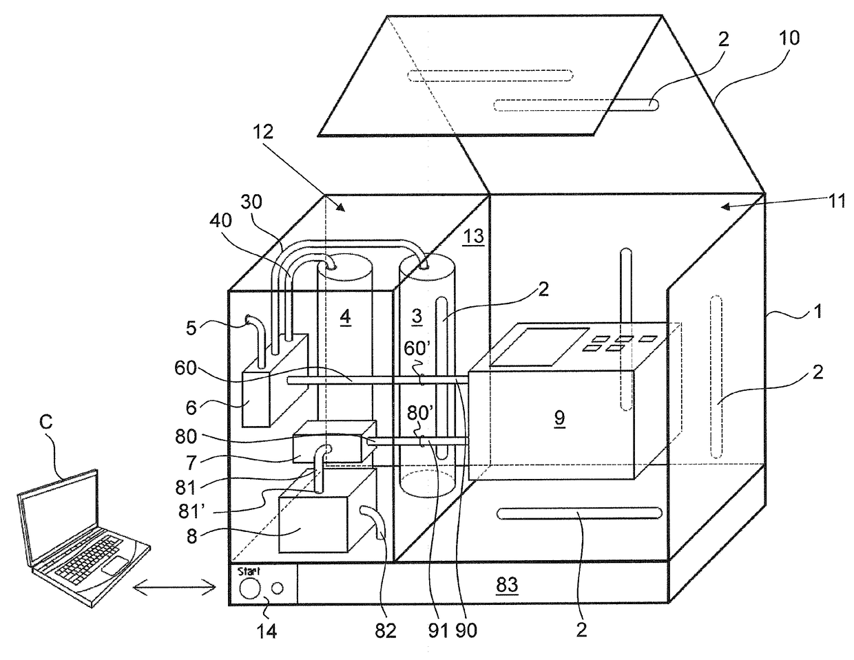
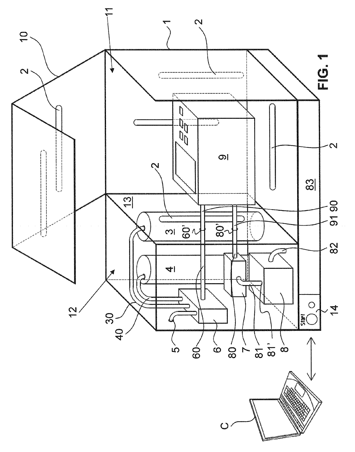
[0037]FIG. 1 shows a first illustrative embodiment of a device according to the invention for cleaning a medical vacuum pump 9. The device has a housing 1. In the housing 1, two chambers 11, 12 are separated from each other by a partition wall 13. One of these chambers is a cleaning chamber 11, into which the medical vacuum pump 9 to be cleaned can be placed. Another chamber is designed as an equipment chamber 12.

[0038]A pivotable lid 10 permits access to the cleaning chamber 11 and closes same. The equipment chamber 12 is preferably likewise closed. It can likewise have a lid that permits access, although this lid is not shown here.

[0039]A fluid collection container 83 is arranged in the floor area of the housing 1 in this example. This fluid collection container 83 is preferably held removably in the housing 1, such that it can be taken out for the purpose of emptying the device.

[0040]An electronic control unit 14 is also arranged in the floor of the housing 1, the control panel h...


PUM

PropertyMeasurementUnit
vacuumaaaaaaaaaa
pressureaaaaaaaaaa
distanceaaaaaaaaaa

Abstract

A device for cleaning a medical vacuum pump, wherein the medical vacuum pump has a suction connector and an air removal opening, which are connected to each other in a fluid-tight manner. The device has a rinsing agent delivery line, connectable to at least one rinsing agent container and having a first port for connection to the suction connector, and a suction line having a second port for connection to the air removal opening and having a vacuum port for connection to a suction source. A rinsing agent can be sucked from the rinsing agent container through the delivery line and via the first port into the medical vacuum pump and from there via the second port through the suction line into an outflow. This device permits simple and rapid cleaning of a vacuum path of medical vacuum pumps.

Description

CROSS-REFERENCE TO RELATED APPLICATION[0001]The present application is the US national phase of International Patent Application No. PCT / EP2015 / 056936, filed Mar. 31, 2015, which application claims priority to European Application No. EP 14163495.6, Apr. 4, 2014. The priority application, EP14163495.6, is hereby incorporated by reference.TECHNICAL FIELD[0002]The present invention relates to a device for cleaning a medical vacuum pump.PRIOR ART[0003]Reusable portable drainage pumps, e.g. for wound drainage or for thorax drainage, have to be cleaned after use, before they can be used again for the next patient. The housing of the pump is usually wiped and disinfected. The interior of the pump, in particular the internal hoses or the entire vacuum path, cannot be cleaned. It is therefore customary to protect the interior of the pump and the internal hoses by means of a bacteria filter and overflow filter. However, this protection by filters is often inadequate in practice. Small partic...

Claims


Application Information

Patent Timeline
Patent Type & Authority Applications(United States)
IPC IPC(8): A61M1/00B08B9/023B08B9/032A61L2/10F04B37/14F04B23/02A61L2/18A61L2/24B08B7/00B08B9/035
CPCA61M1/0066B08B7/0057B08B9/023B08B9/0328B08B9/0325B08B9/035A61L2202/17F04B23/02A61L2/18A61L2/24A61L2/10A61M2209/10A61L2202/24F04B37/14B08B9/00F04B41/02A61M1/062A61M1/80
Inventor EHLERT, HILMAR
Owner MEDELA HLDG AG
Why Eureka
Try Eureka