

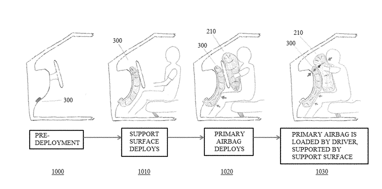
Support surface for primary airbag in vehicle
a primary airbag and support surface technology, applied in the field of vehicle safety, can solve the problems of occupant head sliding, a-pillar or door trim, traditional frontal restraints not providing a sufficient level of protection for occupants, etc., and achieve the effect of augmenting the protective area of the primary airbag
- Summary
- Abstract
- Description
- Claims
- Application Information
AI Technical Summary
Benefits of technology
Problems solved by technology
Method used
Image

Examples
Embodiment Construction
[0029]The terminology used herein is for the purpose of describing particular embodiments only and is not intended to be limiting of the disclosure. As used herein, the singular forms “a”, “an” and “the” are intended to include the plural forms as well, unless the context clearly indicates otherwise. It will be further understood that the terms “comprises” and / or “comprising,” when used in this specification, specify the presence of stated features, integers, steps, operations, elements, and / or components, but do not preclude the presence or addition of one or more other features, integers, steps, operations, elements, components, and / or groups thereof. As used herein, the term “and / or” includes any and all combinations of one or more of the associated listed items. The term “coupled” denotes a physical relationship between two components whereby the components are either directly connected to one another or indirectly connected via one or more intermediary components.
[0030]It is un...
PUM
 Abstract
Description
Claims
Application Information