
Interior cooling configurations in turbine rotor blades

Active Publication Date: 2017-06-22
GENERAL ELECTRIC CO
View PDF8 Cites 7 Cited by
  • Summary
  • Abstract
  • Description
  • Claims
  • Application Information

AI Technical Summary

Benefits of technology

The patent text describes a turbine rotor blade with a unique cooling configuration that includes a cooling channel for directing a coolant through the blade. The cooling channel includes fluidly connected segments, including a supply segment, a cutter tooth segment, and branching segments. The branching segments extend between an upstream port and an outlet port on a target surface area, and are designed to bisect a target interior region. The technical effect is improved cooling for the turbine rotor blade, which helps to increase efficiency and durability.

Problems solved by technology

During operation, because of the extreme temperatures of the hot-gas path, the velocity of the working fluid, and the rotational velocity of the engine, the blades within the turbine become highly stressed with extreme mechanical and thermal loads.
While several strategies for increasing the efficiency of gas turbines are known, it remains a challenging objective because such alternatives—which, for example, include increasing the size of the engine, increasing the temperatures through the hot-gas path, and increasing the rotational velocities of the rotor blades—generally place additional strain on blades and other hot-gas path components parts that are already highly stressed.
First, the use of cooling air decreases the efficiency of the engine.
As a result, the usage of such air necessarily decreases the air available for combustion and, thereby, decreases overall efficiency.
These new designs also create spatial constraints that hinder or constrain the manufacture of traditional cooling channel configurations using conventional approaches.

Method used


Image

  • Interior cooling configurations in turbine rotor blades
  • Interior cooling configurations in turbine rotor blades
  • Interior cooling configurations in turbine rotor blades

Examples


Embodiment Construction

[0027]Aspects and advantages of the present application are set forth below in the following description, or may be obvious from the description, or may be learned through practice of the invention. Reference will now be made in detail to present embodiments of the invention, one or more examples of which are illustrated in the accompanying drawings. The detailed description uses numerical designations to refer to features in the drawings. Like or similar designations in the drawings and description may be used to refer to like or similar parts of embodiments of the invention. As will be appreciated, each example is provided by way of explanation of the invention, not limitation of the invention. In fact, it will be apparent to those skilled in the art that modifications and variations can be made in the present invention without departing from the scope or spirit thereof. For instance, features illustrated or described as part of one embodiment may be used on another embodiment to ...


PUM


Abstract

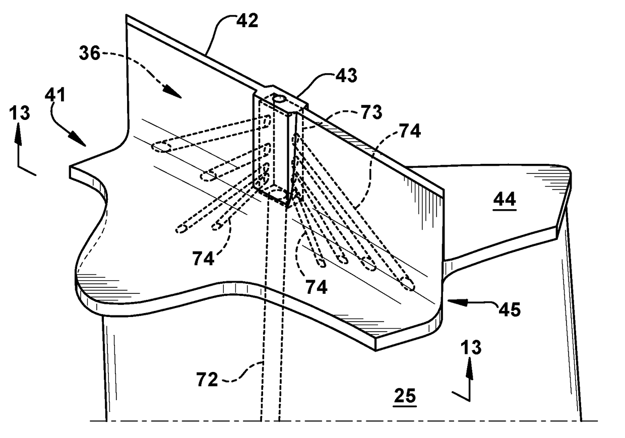
A turbine rotor blade that includes: an airfoil defined between a pressure face and a suction face; a tip shroud that includes a seal rail projecting from an outboard surface and, formed thereon, a cutter tooth; and a cooling configuration that includes a cooling channel for receiving and directing a coolant through an interior of the rotor blade. The cooling channel may include fluidly connected segments, in which: a supply segment extends radially through the airfoil; a cutter tooth segment is formed within the cutter tooth of the seal rail; and branching segments formed within at least one of the tip shroud and an outboard region of the airfoil. Each of the branching segments may extend between an upstream port, which connects to the cutter tooth segment, and an outlet port, which is formed on a target surface area, so that the branching segment bisects a target interior region.

Description

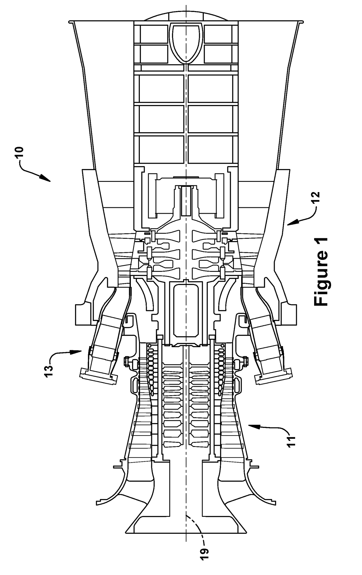
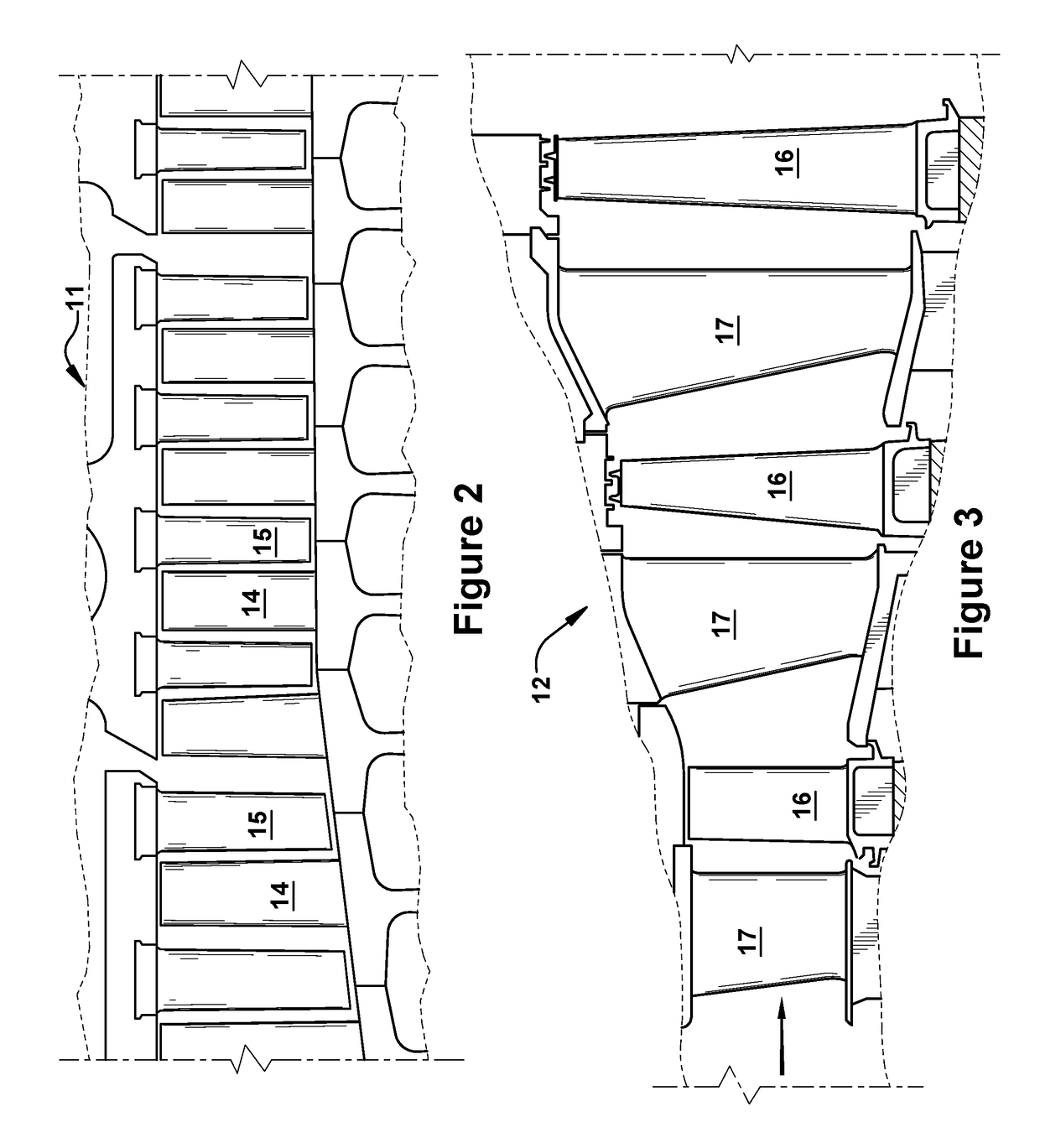
BACKGROUND OF THE INVENTION[0001]This present application relates to interior cooling channels and configurations of the blades in gas turbine engines. More specifically, but not by way of limitation, the present application relates to interior cooling channels and structural configurations formed near the outer radial tip of turbine rotor blades.[0002]It will be appreciated that combustion or gas turbine engines (“gas turbines”) include compressor and turbine sections in which rows of blades are axially stacked in stages. Each stage includes a row of circumferentially-spaced stator blades, which are fixed, and a row of rotor blades, which rotate about a central turbine axis or shaft. In operation, generally, the compressor rotor blades rotate about the shaft, and, acting in concert with the stator blades, compress a flow of air. The supply of compressed air then is used in a combustor to combust a supply of fuel. The resulting flow of hot expanding gases from the combustion, i.e., ...

Claims


Application Information

Patent Timeline
IPC IPC(8): F01D5/18F01D5/20
CPCF01D5/18F01D5/20F05D2240/55F05D2240/307F05D2260/20F05D2220/32F01D5/189F01D5/187F01D5/225F05D2260/202Y02T50/60
Inventor CHOUHAN, ROHITGOOD, RANDALL RICHARDMISTRY, HITESHKUMAR RAMESHCHANDRAJAISWAL, SHASHWAT SWAMI
Owner GENERAL ELECTRIC CO
Learn More