
Refrigerator

Active Publication Date: 2017-06-22
SAMSUNG ELECTRONICS CO LTD
View PDF20 Cites 13 Cited by
  • Summary
  • Abstract
  • Description
  • Claims
  • Application Information

AI Technical Summary

Benefits of technology

This patent describes a refrigerator that can better control the temperature inside and more efficiently defrost using multiple heaters and fans. The technology also prevents the temperature inside the refrigerator from increasing by reducing the time needed for defrosting. Additionally, if the refrigerator is opened to allow air to flow, the controller can close the opening to prevent excessive air from entering, which could lead to the refrigerant being introduced into the trap part. The controller uses data from a temperature sensor to adjust the output of the defrosting heater based on the measured temperature inside the refrigerator. This ensures that the defrosting process is efficient and effective while minimizing energy usage.

Problems solved by technology

However, according to technology of Japanese Patent Laid-open Publication No. 2010-216680, since the defrosting process is achieved by controlling the heater using a predetermined pattern, a time needed to finish defrosting is consumed, such that there is a high possibility of increasing a temperature of the inner space of the refrigerator during the defrosting process.
Therefore, there is a high probability that food or beverages stored in the refrigerator become rotten.
Therefore, the conventional refrigerator unavoidably stops the defrosting process although the defrosting process must be continuously performed, such that a heater output level for such defrosting may be deteriorated.

Method used


Image

  • Refrigerator
  • Refrigerator
  • Refrigerator

Examples


first embodiment

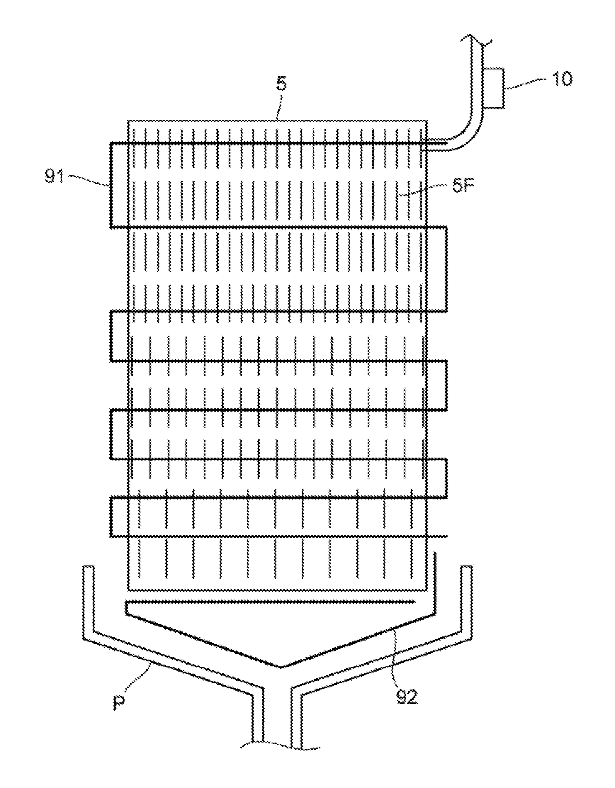
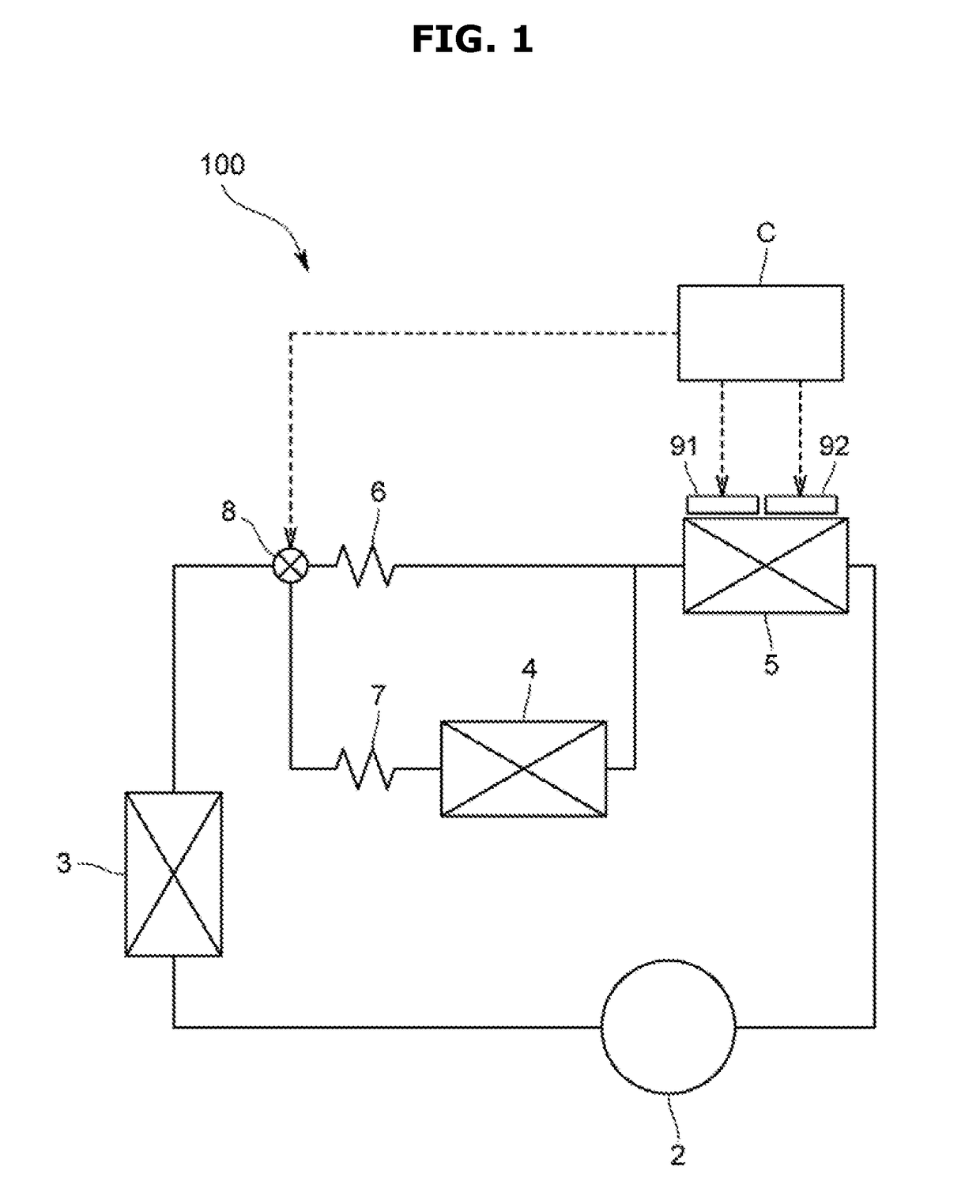
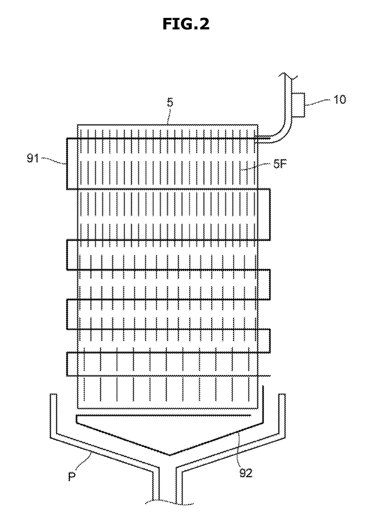
[0090]In the above-mentioned refrigerator 100 the refrigerant supply state may be switched by the flow passage switching valve 8 on the basis of the temperature detected by the evaporator temperature sensor 10, and at the same time the output of the upper heater 91 and the output of the lower heater 92 may be controlled in a stepwise manner. As a result, the defrosting operation time can be reduced and the increase of the inner temperature of the refrigerator can be prevented.

[0091]In more detail, if the measured temperature is less than the first temperature (T1), the refrigerant flows to the freezing evaporator 5, and at the same time the output of the upper heater 91 and the output of the lower heater 92 can be maximized, such that the defrosting operation time for removing frost of the freezing evaporator 5 may be reduced.

[0092]In addition, if the measured temperature is equal to or higher than the first temperature (T1), the refrigerant does not flow in the freezing evaporator...

second embodiment

[0093]A refrigerator 100 according to the present disclosure will hereinafter be described with reference to FIGS. 4 and 5.

[0094]Although the refrigerator 100 according to the second embodiment includes the same constituent elements as those of the refrigerator 100 of the first embodiment, control content of the defrosting operation of the second embodiment is different from that of the first embodiment.

[0095]If the operation mode is switched from the common cooling operation to the defrosting operation, the controller C may open the freezing-chamber port of the flow passage switching valve 8. In addition, it does not matter whether the refrigerating-chamber port is opened or closed. However, in order to remove a pressure difference between the suction part and the discharge part of the compressor 2, it may be more preferable that the refrigerating-chamber port be opened.

[0096]The controller C may drive the upper heater 91 and the lower heater 92 so that the output levels of the upp...

third embodiment

[0107]The refrigerator 100 of the third embodiment will hereinafter be described with reference to FIGS. 6 and 7.

[0108]Although the constituent elements of the refrigerator 100 according to the third embodiment are identical to those of the first embodiment, control content of the refrigerator 100 of the third embodiment is different from that of the first embodiment.

[0109]If the operation mode is switched from the common cooling operation mode to the defrosting mode, the controller C may open the freezing-chamber port of the flow passage switching valve 8. In addition, it does not matter whether the refrigerating-chamber port is opened or closed. However, in order to remove a pressure difference between the suction part and the discharge part of the compressor 2, it may be more preferable that the refrigerating-chamber port be opened.

[0110]The controller C may operate the upper heater 91 and the lower heater 92 to maximize the output of the upper heater 91 and the output of the low...


PUM


Abstract

A refrigerator includes a storage chamber, an evaporator configured to cool the storage chamber, and an air passage through which cold air generated by the evaporator flows. The air passage includes a blower fan configured to blow the cold air to the storage chamber, and a trap part in which warm air generated by a defrosting operation stays, such that warm air generated by the defrosting operation is prevented from being introduced into the inner space of the refrigerator through the air passage. The refrigerator reduces the defrosting operation time, efficiently prevents increase of the inner temperature of the refrigerator due to warm air during the defrosting operation, reduces a temperature difference in inner temperature of the refrigerator, and prevents food stored in the refrigerator from being rotten due to a temperature change.

Description

CROSS-REFERENCE TO RELATED APPLICATIONS[0001]This application claims the benefit of Korean Patent Application No. 10-2016-0095021, filed on Jul. 26, 2016 in the Korean Intellectual Property Office, the disclosure of which is incorporated herein by reference.[0002]This application claims the benefit of Japanese Patent Application No. 2015-246469, filed on Dec. 17, 2015 in the Japanese Patent Office, the disclosure of which is incorporated herein by reference.[0003]This application claims the benefit of Japanese Patent Application No. 2015-255166, filed on Dec. 25, 2015 in the Japanese Patent Office, the disclosure of which is incorporated herein by reference.[0004]This application claims the benefit of Japanese Patent Application No. 2016-076994, filed on Apr. 7,2016 in the Japanese Patent Office, the disclosure of which is incorporated herein by reference.[0005]This application claims the benefit of Japanese Patent Application No. 2016-099295, filed on May 18, 2016 in the Japanese P...

Claims


Application Information

Patent Timeline
IPC IPC(8): F25D21/00F25D17/06F25D17/04F25D21/08
CPCF25D21/002F25D21/08F25D17/062F25D2600/04F25D17/045F25D2317/063F25D2600/02F25D17/065F25B49/02F25B2400/23F25B2700/2103F25B2700/2117F25D2317/067F25D2317/0682F25B2700/11F25D2317/0684F25B41/20F25B2500/26F25B2600/2507F25D17/06F25B39/02F25D21/06F25D29/00
Inventor IWAMOTO, TOMOHARUSHIMIZU, KAZUOMORI, AIKOSEO, TATSUYA
Owner SAMSUNG ELECTRONICS CO LTD
Learn More