Electromagnetic cloaking structure and method for manufacturing the same

a technology of cloaking structure and cloaking method, which is applied in the direction of optical elements, instruments, camouflage devices, etc., can solve the problems of difficult anisotropic material parameters production, difficult to achieve the structure, and complicated nanometer-order structure manufacturing

Active Publication Date: 2017-06-22
FUJIFILM CORP
View PDF0 Cites 1 Cited by
  • Summary
  • Abstract
  • Description
  • Claims
  • Application Information

AI Technical Summary

Benefits of technology

[0010]The invention has been made in view of the above-mentioned problems and an object of the invention is to provide a feasible transmissive cloaking structure.

Problems solved by technology

It is difficult to produce the anisotropic material parameters using the current technique.
In particular, in a case in which cloaking is performed in a visible range, it is necessary to manufacture a cubic and complicated nanometer-order structure.
Therefore, it is difficult to achieve the structure, using the current leading-edge semiconductor process technique.

Method used


Image

  • Electromagnetic cloaking structure and method for manufacturing the same
  • Electromagnetic cloaking structure and method for manufacturing the same
  • Electromagnetic cloaking structure and method for manufacturing the same

Examples


example 1

[0087](Optical Structure Design)

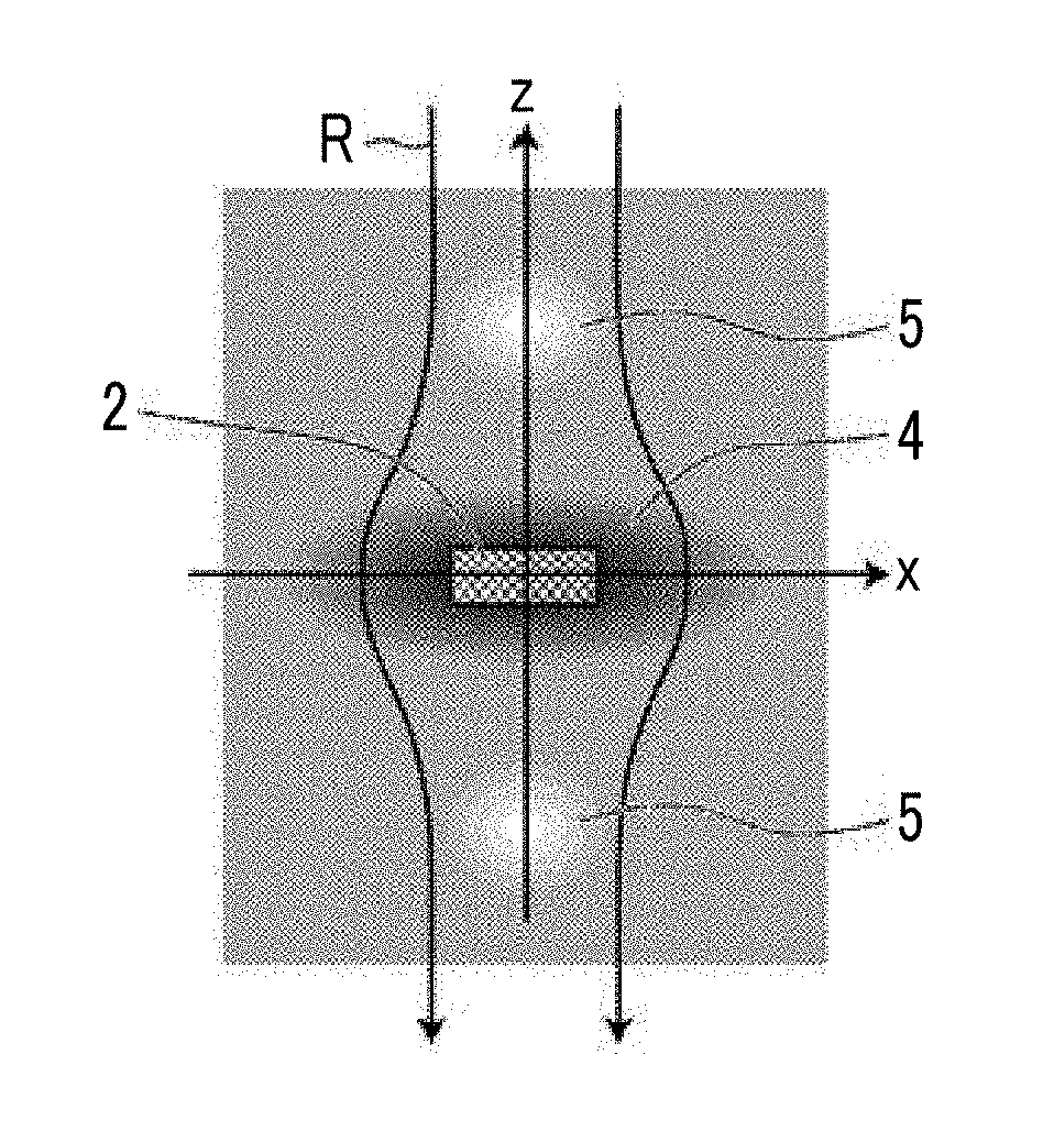
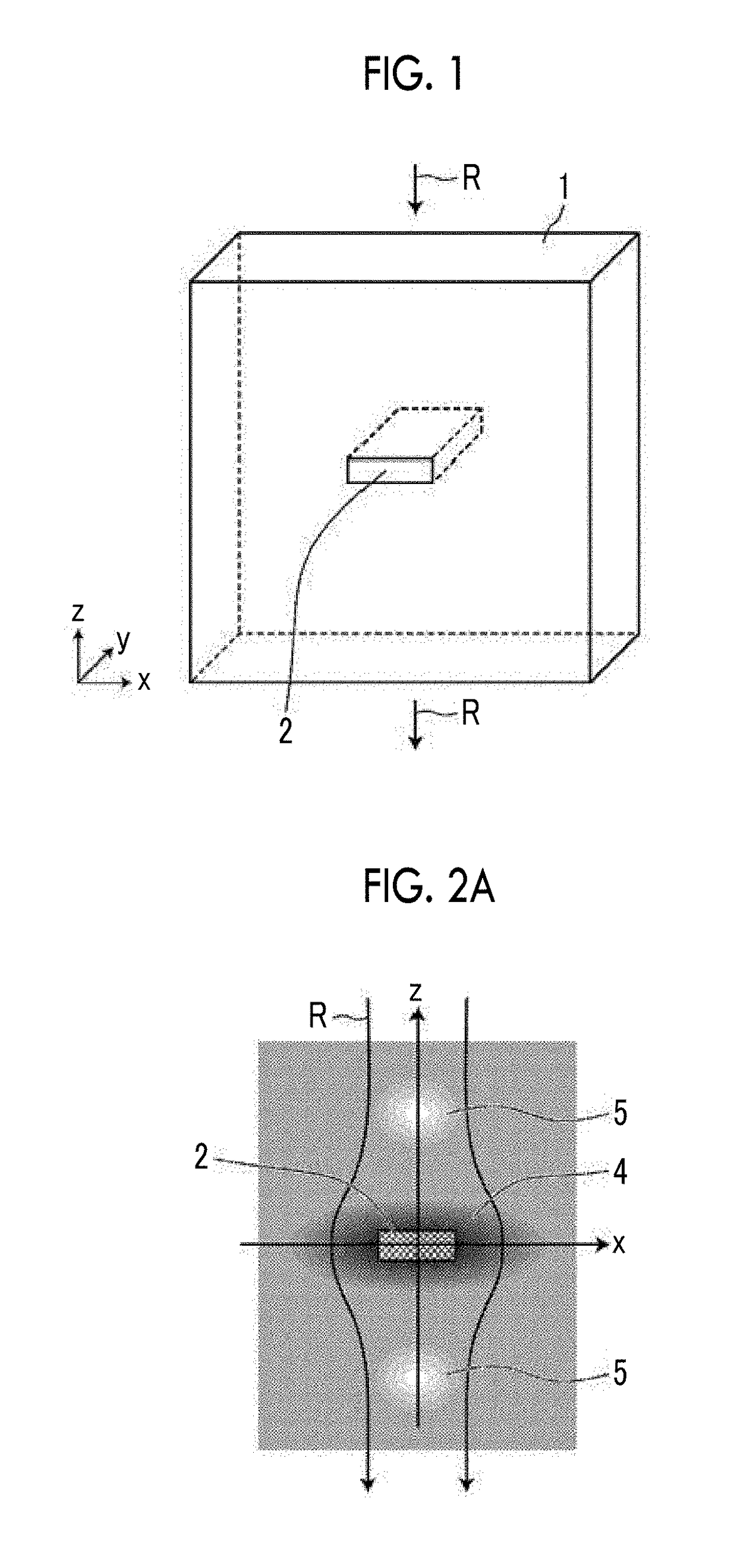
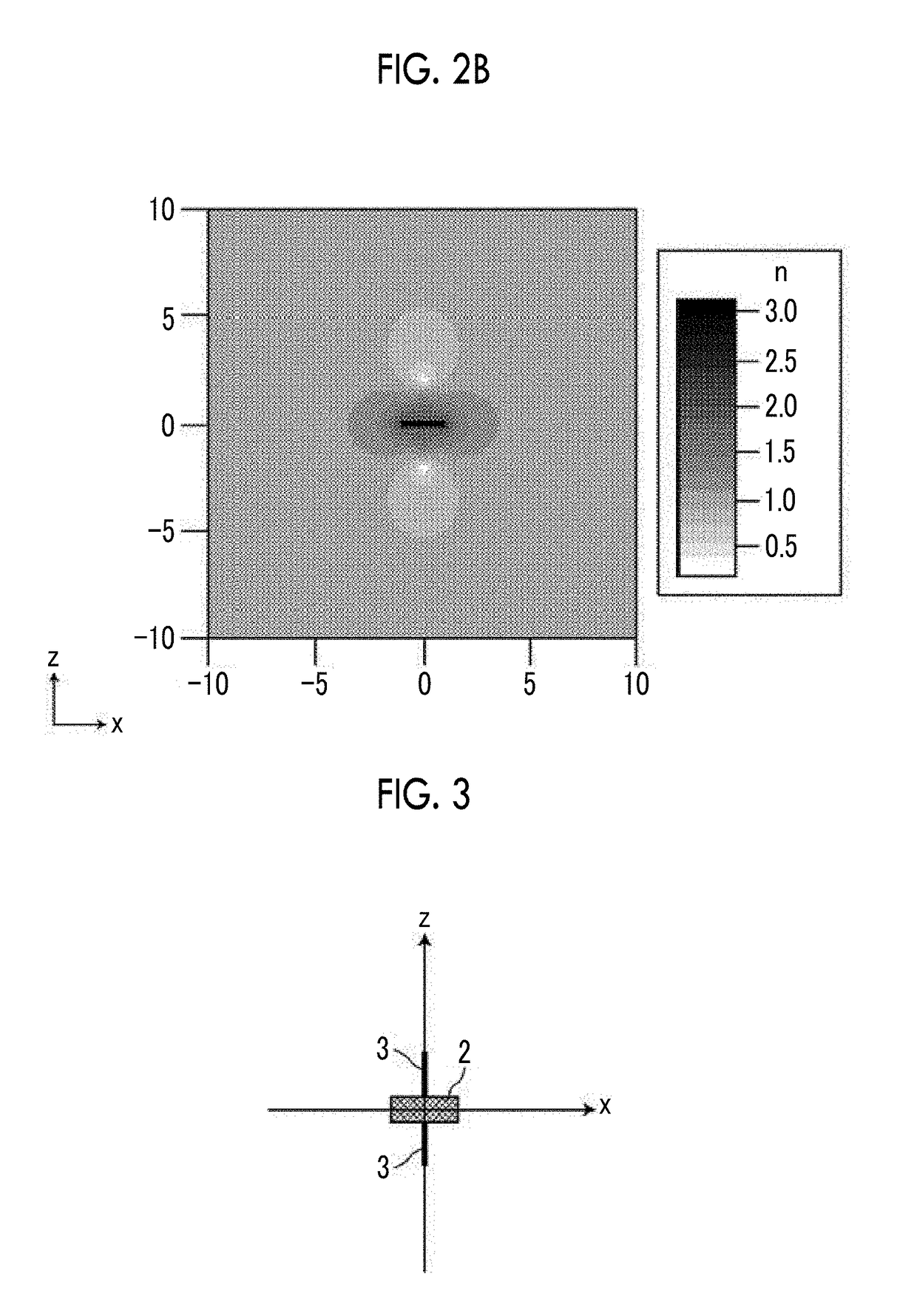
[0088]A model in which a shielding space with a rectangular parallelepiped shape having a long side length (x direction) of 2 μm, a short side length (z direction) of 0.2 μm, and a depth (the y direction in the drawings) of 0.05 μm was set at the center of a rectangular parallelepiped having a size of 20 μm in the x direction, 20 μm in the z direction, and 0.05 μm in the y direction and spaces having the same shape were periodically and infinitely repeated in the xy direction was assumed. Since the xy direction is a periodic boundary, calculation is performed for a model in which shielding spaces that are infinitely long in the y direction are infinitely arranged in the x direction at an interval of 20 μm. In this model, a refractive index distribution is constant in the depth direction (y direction). Therefore, when the refractive index distribution is calculated, the model may be considered as a two-dimensional model in the xz plane.

[0089]The follow...

example 2

[0107](Optical Structure Design)

[0108]In Example 2, an electromagnetic cloaking structure having the refractive index distribution described in the second embodiment which was disposed only on the incident side of electromagnetic waves with respect to the plane in which the incident direction of the electromagnetic waves on a target object to be shielded from the electromagnetic waves was a normal vector was examined.

[0109]First, a refractive index distribution was calculated using a space model that was the same as the space model according to Example 1 except that a shielding space had a rectangular parallelepiped shape with a long side length (x direction) of 2 μm, a short side length (z direction) of 0.4 μm, and a depth (the y direction in the drawings) of 0.05 μm.

[0110]That is, it was assumed that, in a two-dimensional model, a shielding space had a rectangular shape (the x direction: 2 μm, the z direction: 0.4 μm) and linear slits were provided in the forward and backward dire...


PUM


Abstract

In an electromagnetic cloaking structure, a refractive index distribution has a high refractive index region which is provided around a shielding space and has a maximum value in a plane surrounding the shielding space and in which a refractive index decreases gradually from the centroid of the shielding space along a radial line passing through the plane so as to be close to an average refractive index and a low refractive index region which has a minimum value at two points having the shielding space and the high refractive index region interposed therebetween on a virtual optical axis passing through the shielding space and in which the refractive index increases gradually from the two points in a direction opposite to the high refractive index region on the virtual optical axes, on which the two points are placed, so as to be close to the average refractive index.

Description

CROSS REFERENCE TO RELATED APPLICATIONS[0001]The present application is a Continuation of PCT International Application No. PCT / JP2015 / 004429 filed on Aug. 31, 2015, which claims priority under 35 U.S.C. §119(a) to Japanese Patent Application No. 2014-192386 filed on Sep. 22, 2014. Each of the above applications is hereby expressly incorporated by reference, in its entirety, into the present application.BACKGROUND OF THE INVENTION[0002]1. Field of the Invention[0003]The present invention relates to a technique that shields an object and some space volume from an external observer so as not to be detected, and more particularly, to an electromagnetic cloaking structure and a method for manufacturing the same.[0004]2. Description of the Related Art[0005]There are many reports on attempts to shield an object from electromagnetic waves (including visible light). The observer detects a target object, using disturbance in electromagnetic waves caused by the scattering, reflection, or abso...

Claims


Application Information

Patent Timeline
Patent Type & Authority Applications(United States)
IPC IPC(8): G01S7/495G02B1/00F41H3/00G01S7/38
CPCG01S7/495F41H3/00G02B1/002G01S7/38H01Q15/0086
Inventor OHTSU, AKIHIKOYASUDA, HIDEKI
Owner FUJIFILM CORP
Why Eureka
Try Eureka