Predictive memory maintenance

a memory array and memory technology, applied in the direction of redundancy hardware error correction, input/output to record carriers, instruments, etc., can solve the problem of memory array memory die failur

Active Publication Date: 2017-06-22
INTEL CORP
View PDF13 Cites 46 Cited by
  • Summary
  • Abstract
  • Description
  • Claims
  • Application Information

AI Technical Summary

Problems solved by technology

A memory die of the memory array may fail due to various causes.

Method used


Image

  • Predictive memory maintenance
  • Predictive memory maintenance
  • Predictive memory maintenance

Examples


examples

[0056]The following examples pertain to further embodiments.

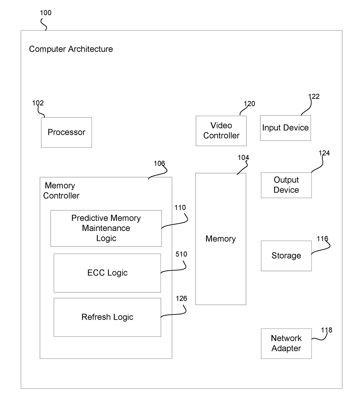
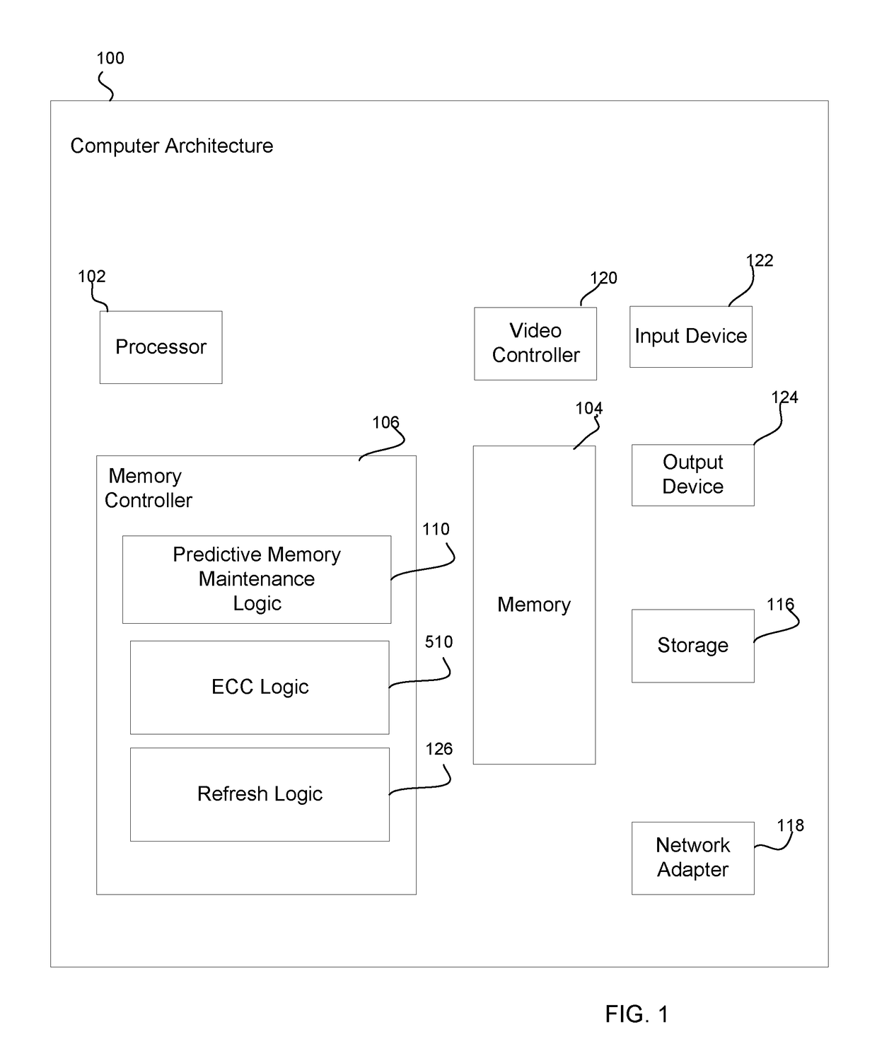
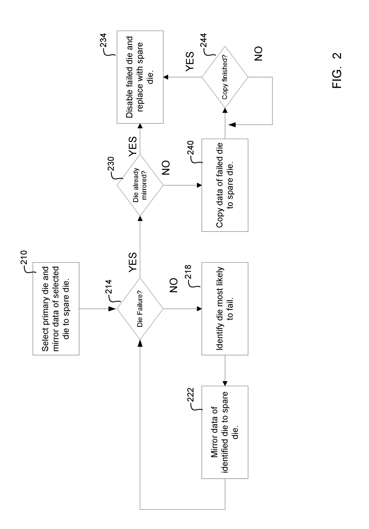
[0057]Example 1 is an apparatus, comprising:[0058]selection logic configured to determine memory performance of operational memory dies of a memory, and select an operational memory die of the memory as a function of memory die performance; and[0059]data mirror logic configured to mirror data for the selected operational memory die to a spare memory die.

[0060]In Example 2, the subject matter of Examples 1-8 (excluding the present Example) can optionally include:[0061]die failure detection logic configured to detect failure of the selected operational memory die; and[0062]die replacement logic configured to, in response detection of the failure of the selected operational memory die, disable the failed operational memory die and replace the failed operational memory die with the spare memory die wherein the spare memory die has data mirrored from the selected operational memory die prior to a detection of a failure of the se...


PUM


Abstract

Predictive memory maintenance in accordance with one aspect of the present description, can anticipate a failure of a selected primary memory die of an array, and pre-load a spare memory die with the data of the selected primary memory die deemed to have a likelihood of failure, prior to any actual failure of the selected memory die. In the event that the selected primary memory die does subsequently fail, the spare memory die pre-loaded with the data of the selected primary memory die can readily take the place of the failed primary memory die with a pre-existing copy of the data of the failed primary memory die. Other aspects are described herein.

Description

TECHNICAL FIELD[0001]The present invention relates generally to devices having spare memory dies.BACKGROUND[0002]Random access memories (RAMs) often utilize multiple memory dies in which each memory die has a separate semiconductor substrate on which a memory integrated circuit is fabricated. The memory dies are frequently arranged in an array of dies in which the total data storage capacity of the memory array is sum of the storage capacity of each individual memory die added together.[0003]A memory die of the memory array may fail due to various causes. A flash memory may employ a feature often referred to as “die sparing” in which an extra memory die is provided to replace a primary memory die in the event that one of the primary memory dies fails. For example, the memory array may have ten primary memory dies in which the system stores data into and reads data from in connection with regular data input / output operations. An extra memory die may be included in the array as a spar...

Claims


Application Information

Patent Timeline
Patent Type & Authority Applications(United States)
IPC IPC(8): G06F3/06G06F11/20
CPCG06F3/0619G06F11/2069G06F3/0679G06F3/065G06F11/1658G06F11/1666G06F11/20G11C29/006G11C29/808
Inventor MILLER, SHAUN M.MANGOLD, RICHARD P.
Owner INTEL CORP
Why Eureka
Try Eureka