Adaptive high frequency energy detection

a high frequency energy and detection technology, applied in the field of vibration data collection and analysis, can solve the problems of increasing higher frequency vibration, causing “clicking” to occur, and generating different frequency patterns of parts, and achieve the effect of easy analogization and readily changing

Inactive Publication Date: 2005-03-15
ROCKWELL AUTOMATION
View PDF27 Cites 40 Cited by
  • Summary
  • Abstract
  • Description
  • Claims
  • Application Information

AI Technical Summary

Benefits of technology

This digital methodology for high frequency analysis produces a resulting peak-detected output signal that is easily analogized to those produced using analog circuitry in known data collectors. Accordingly, users that are knowledgeable in the analysis of peak-detected waveforms produced by prior data collectors, may readily reapply this knowledge to the peak-detected digital output signal produced in accordance with principles of the present invention.
It is a significant aspect of the present invention that the decay factors used in computing the maximum peak-to-peak value and peak negative value are determined by the digital signal processing circuit and may be readily changed. As a consequence, high frequency processing performed by the digital signal processing circuit may be readily adapted to the particular frequency characteristics of the machine being analyzed for predictive maintenance. Importantly, this adaptation may be made without any modification to the analog circuitry of the data collector.

Problems solved by technology

If, however, a bearing or other mechanical system begins to fail, the part will begin to generate different frequency patterns.
For example, a bearing may develop a crack, causing a “click” to occur each time weight is applied to the crack in the bearing, which will be reflected as increased higher frequency vibration in a vibration signal from the machine.
Alternatively, a sliding mechanical part may begin to fail and scrape undesirably as it moves, again causing increased higher frequency vibration.
Thus, this transducer is most sensitive to “shock pulse” signals in this frequency band, which are often indicative of bearing defects and poor lubrication.
A difficulty inherent in the various high frequency energy detection methods described above is their lack of flexibility.
Alternatively, the filters and detectors in the data collector may be made adjustable, but this would also require complexity, namely, in the filters and detectors, analog switches would need to be included to select between circuit components of different values, in order to change the frequency bands and time constants of the circuit.
This approach may also encounter problems with noise due to the number of switches that are included in the analog signal path.

Method used


Image

  • Adaptive high frequency energy detection
  • Adaptive high frequency energy detection
  • Adaptive high frequency energy detection

Examples


Embodiment Construction

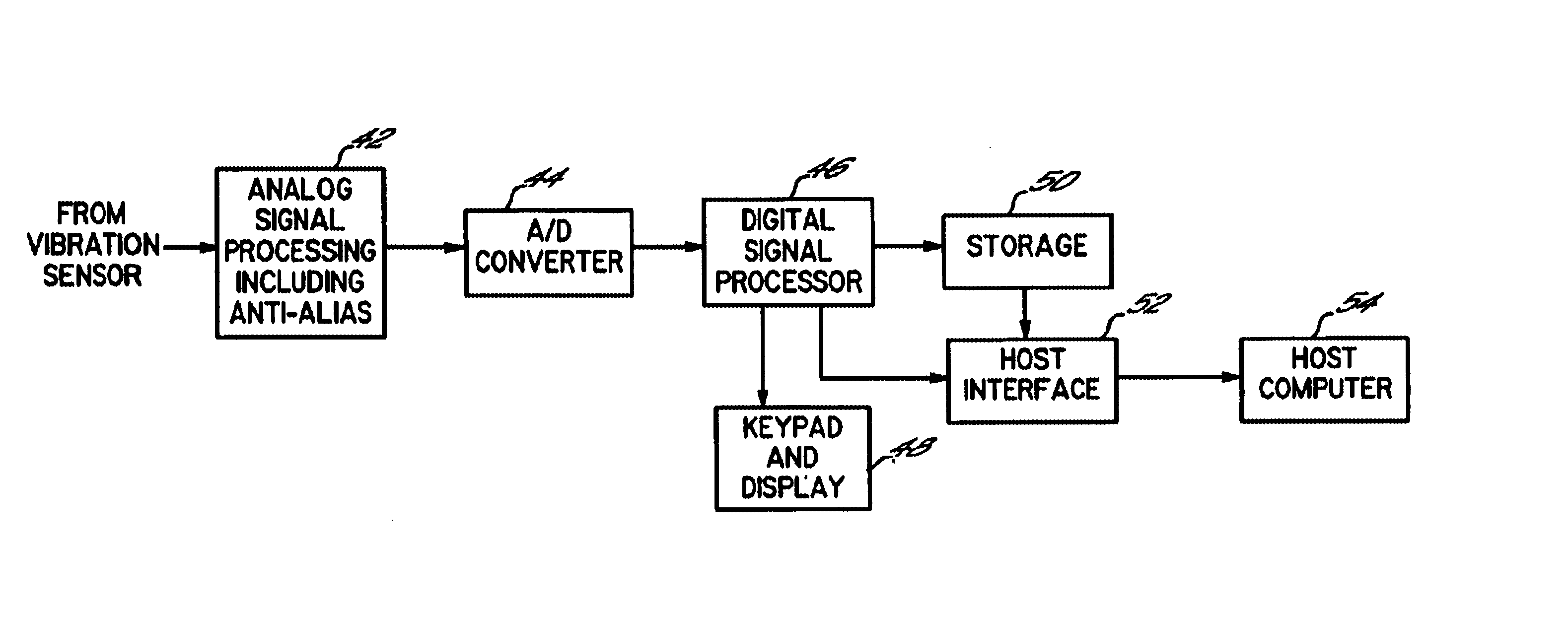
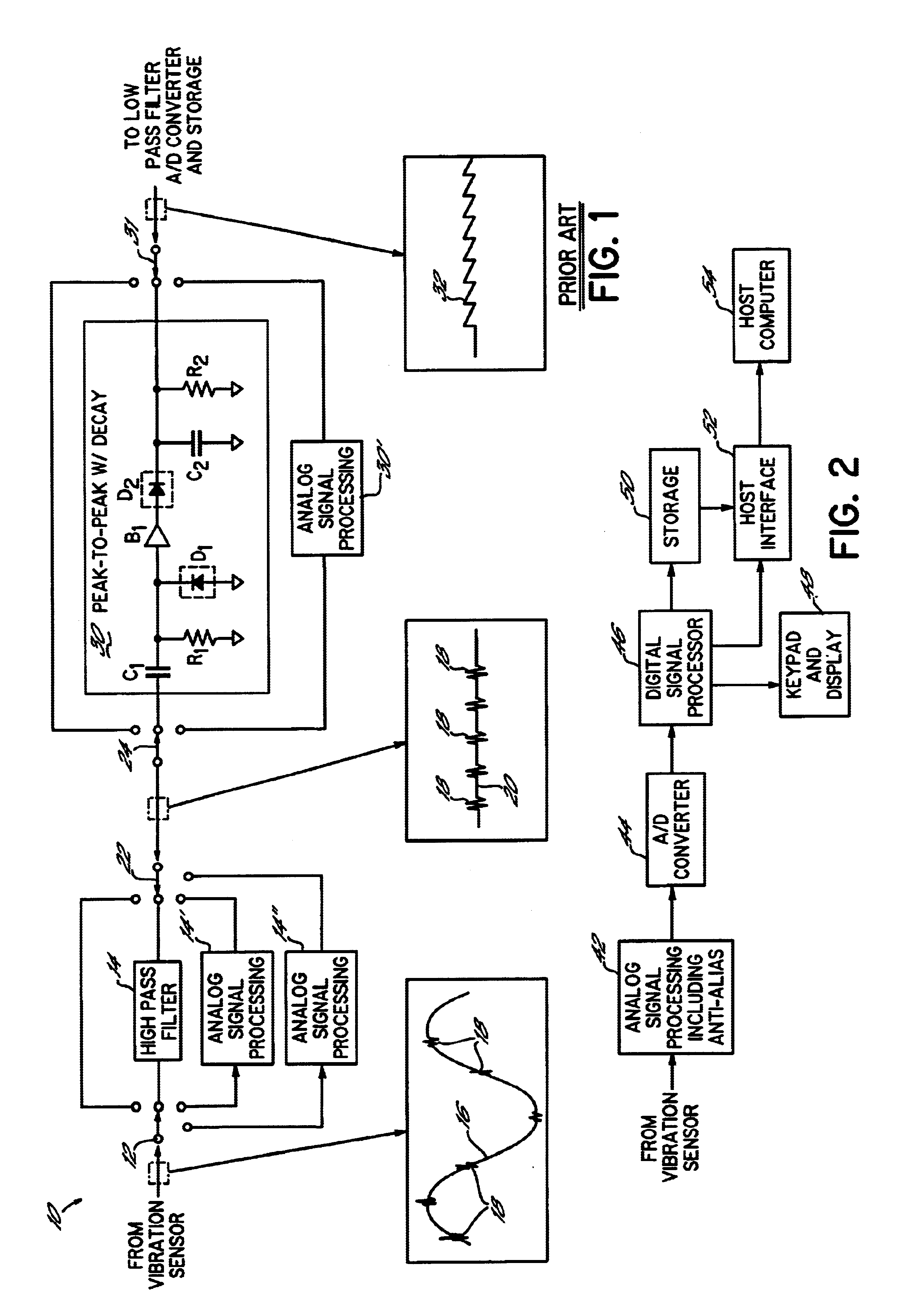
Referring now to FIG. 2, a data collector 40 in accordance with principles of the present invention can be described. Functional blocks of the data collector are illustrated in FIG. 2 to facilitate the description of the operations contemplated by the present invention. It will be appreciated, however, that a data collector suitable for carrying out the principles of the present invention may take many forms. In one embodiment, a suitable data collector comprises a data collector available from the assignee of the present invention under the model name dataPAC 1500. Another suitable data collector is disclosed in U.S. Pat. No. 5,633,811 issued to Canada et al., and assigned to Computational Systems Incorporated, which describes a data collector sold by Computational Systems Incorporated, the disclosure of which is incorporated herein by reference. Alternatively, another suitable data collector is a palmtop computer having a sound interface card therein for receiving digital vibratio...


PUM


Abstract

A data collector having a digital signal processing circuit that receives a digitized vibration signal, and performs processing steps to isolate high frequency pulses in the digitized vibration signal and quantify energy content of those pulses by detecting a peak negative value of the digitized peak-to-peak amplitude of the received vibration signal, and then using this peak negative value to compute a maximum peak-to-peak value of the received vibration signal. Periodically, the maximum peak-to-peak value and peak negative value are reduced in magnitude by a decay factor, such that the peak negative value and maximum peak-to-peak value decay over time. The decay factors used in computing the maximum peak-to-peak value and peak negative value are determined by the digital signal processing circuit and may be readily changed. As a consequence, high frequency processing performed by the digital signal processing circuit may be readily adapted to the particular frequency characteristics of the machine being analyzed for predictive maintenance, without modification of the analog circuitry of the data collector. The resulting maximum peak-to-peak value comprises a peak-detected digital output signal that may be stored and / or displayed to a user as a reflection of the high frequency content of the vibration signal, or frequency transformed for storage and / or display to a user.

Description

FIELD OF THE INVENTIONThe invention relates to collection and analysis of vibration data for the purposes of predictive maintenance.BACKGROUND OF THE INVENTIONThere are many well known methods for collecting vibration data for performing predictive maintenance. Typically, in these methods a vibration sensor such as a piezoelectric accelerometer is mechanically coupled to the machine to be monitored. The vibration sensor collects vibrations from the machine and converts these vibration to an electrical signal. The electrical signal is processed by suitable signal processing and converted from analog to digital form. The resulting digital signal is stored for later analysis.Analysis of a vibration signal from a machine typically involves one or both of (1) comparing that signal to previously collected signals to identify an variations that would be indicative of machine wear and possible impending failure, and (2) forming a frequency spectrum of the vibration signal and evaluating thi...

Claims


Application Information

Patent Timeline
Patent Type & Authority Patents(United States)
IPC IPC(8): G01M7/00G01M7/02
CPCG01M7/025G01N2291/044
Inventor STOUTENBURG, DONN V.XU, MING
Owner ROCKWELL AUTOMATION
Why Eureka
Try Eureka