Sound emitter device

a technology of sound emitter and acoustic membrane, which is applied in the direction of electrical transducers, loudspeaker diaphragm shapes, transportation and packaging, etc., can solve the problems of insatisfactory methods from the industrial point of view, and the production cycle time and cost of such devices no longer meet current market constraints

Active Publication Date: 2017-06-22
APTIV TECH LTD
View PDF1 Cites 3 Cited by
  • Summary
  • Abstract
  • Description
  • Claims
  • Application Information

AI Technical Summary

Benefits of technology

[0004]The present invention aims to solve these problems by proposing a simple and economical solution.

Problems solved by technology

These methods are not satisfactory from the industrial point of view, however.
The production cycle times and costs of such devices no longer satisfy current market constraints.

Method used


Image

  • Sound emitter device
  • Sound emitter device
  • Sound emitter device

Examples


Embodiment Construction

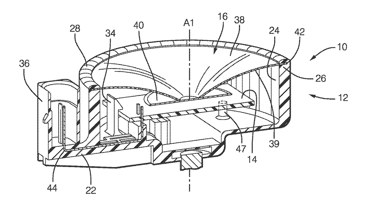
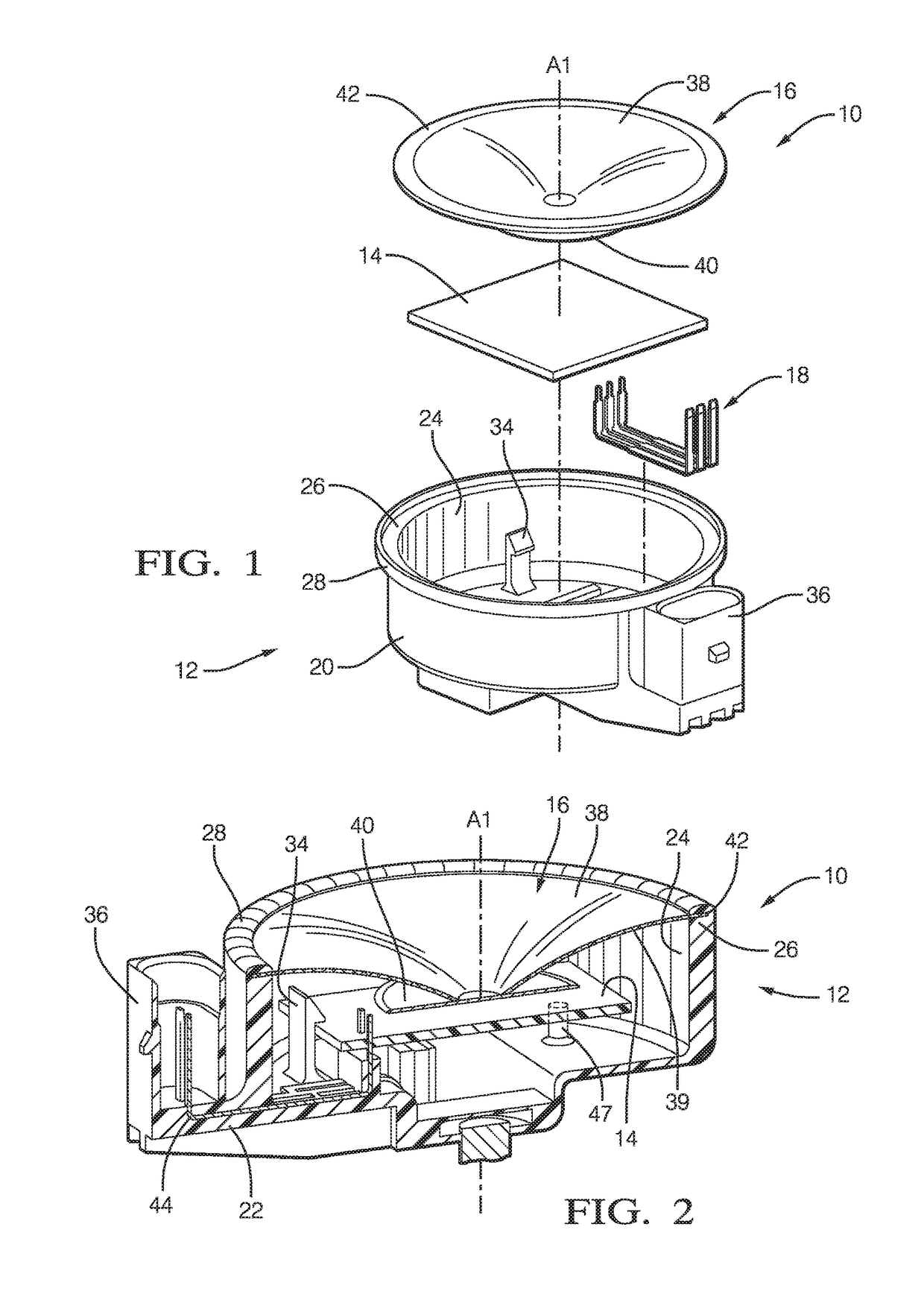
[0025]In FIG. 1 a sound emitter device 10 for use on a motor vehicle (not shown) is represented before it is assembled. The sound emitter device 10 includes a casing 12 receiving the various components of the device, in particular a control circuit 14, a sound-producing assembly 16 and electrical connection means 18.

[0026]The remainder of the description will refer in a non-limiting manner to a vertical downward orientation of the casing 12 along an axis A1, as in FIG. 1. Of course, the casing 12 can be installed in the vehicle in various positions and not exclusively as shown in FIG. 1.

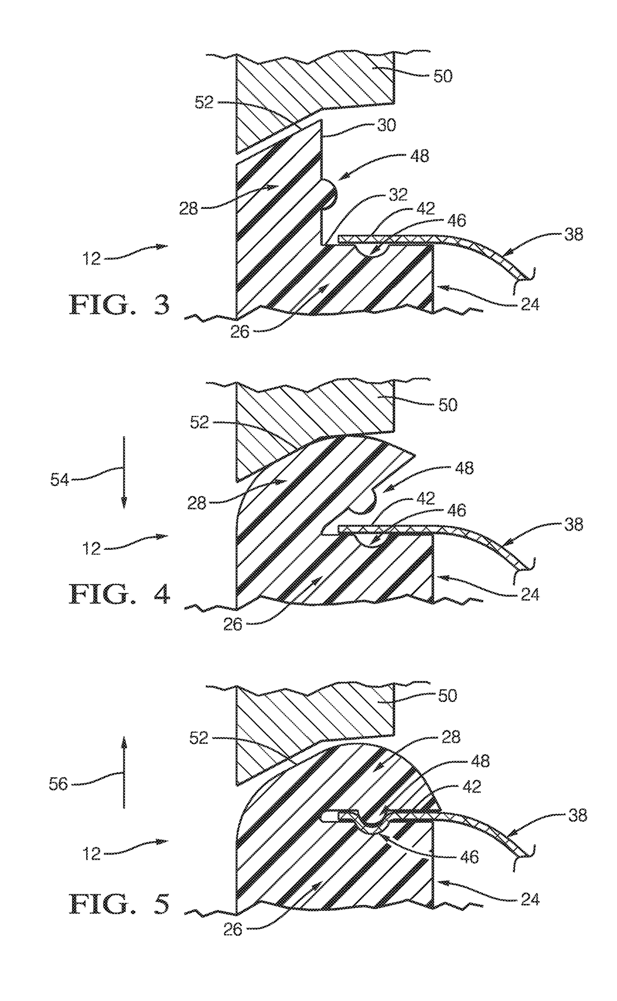
[0027]The casing 12 is formed of a substantially cylindrical axial wall 20 that here extends along the vertical axis A1 from a transverse bottom wall 22 toward an upper opening 24. The upper opening 24 is preferably substantially circular. The axial wall 20 of the casing 12 includes an external peripheral rim 26 arranged in the upper opening 24. As shown, the peripheral rim 26 occupies the entire per...


PUM


Abstract

A sound emitter device for use on a motor vehicle comprises a casing comprising an axial wall and a bottom wall, the axial wall extending along a vertical axis from the bottom wall toward an opening opposite the bottom wall, a control circuit, an acoustic membrane that closes the opening of the casing and that is provided on its lower face with excitation means controlled by the control circuit a peripheral rim that is arranged in the opening, the external peripheral edge of the acoustic membrane being mounted to bear on the peripheral rim, a secondary wall that is made in one piece with the peripheral rim and that is bent toward the peripheral rim so as to retain the acoustic membrane by clamping its external peripheral edge between the peripheral rim and the secondary wall.

Description

CROSS-REFERENCE TO RELATED APPLICATION[0001]This application claims the benefit under 35 U.S.C. §119(a) of French Patent Application FR1562634, filed Dec. 17, 2015, the entire disclosure of which is hereby incorporated herein by reference.TECHNICAL FIELD OF INVENTION[0002]This disclosure generally relates to a sound emitter device for use on a motor vehicle, and more particularly relates to the retention of an acoustic membrane of a sound emitter device.BACKGROUND OF INVENTION[0003]Sound emitter devices for use on vehicles and comprising an acoustic membrane are known. Alarm system sirens and sound generating devices for hybrid or electric vehicles are generally equipped with a casing containing a printed circuit board and an acoustic membrane associated with means for exciting the membrane. The free volume of the casing generally forms an acoustic chamber that enables good transmission of vibrations from the membrane to the air outside the sound emitter device to produce the requir...

Claims


Application Information

Patent Timeline
Patent Type & Authority Applications(United States)
IPC IPC(8): H04R1/02H04R7/18B60Q5/00H04R31/00
CPCH04R1/026H04R31/006B60Y2200/92B60Q5/008B60Y2200/91H04R7/18H04R7/22H04R31/003H04R2231/003H04R2307/207H04R2499/13
Inventor KAMON, MICHALTKACZYK, GRZEGORZ
Owner APTIV TECH LTD
Why Eureka
Try Eureka