Electronic storage and transmission device

Inactive Publication Date: 2017-06-22
PHOTOFAST COMPANY
View PDF9 Cites 0 Cited by
  • Summary
  • Abstract
  • Description
  • Claims
  • Application Information

AI Technical Summary

Benefits of technology

The present invention aims to improve the current line-type flash drives that have a larger folded volume and increased manufacturing costs due to the use of wire constraint member or have restraints on the operation freedom and connection angle of the transmission connector. The invention provides a solution to these drawbacks by fixing the connecting wire only on the holding base, allowing the wires to fully expand during data transmitting process and improving the user's operation freedom. The holding base is positioned on the end portion of the storage and transmission body, making it easier to receive the connecting wire and reducing the folded volume of the electronic storage and transmission device. The device combines the functions of data storage and charging electronic products.

Problems solved by technology

However, after the user performed the fold of the connecting wire 50 by using the wire constraint member 70, the line-type flash drive has a larger folded volume; in the other hand, when a manufacturer manufactures the line-type flash drive, they need to consider design and manufacture of the wire constraint member 70, overall manufacturing cost of the current line-type flash drive is thereby increased.
However, due to the part of the connecting wire 50A fixed in the receiving slot 41, the connecting wire 50A cannot be fully expanded in data transmitting process, that restrains operation freedom and connection angle of the transmission connector 60A connecting to the electronic product, inconvenience is thus caused when the user uses this line-type flash drive.

Method used


Image

  • Electronic storage and transmission device
  • Electronic storage and transmission device
  • Electronic storage and transmission device

Examples


Embodiment Construction

[0027]The technical means employed by the present invention to achieve the aforesaid aspect will be further elaborated with accompanying drawings and preferred embodiments as follows.

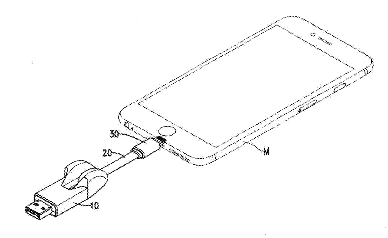
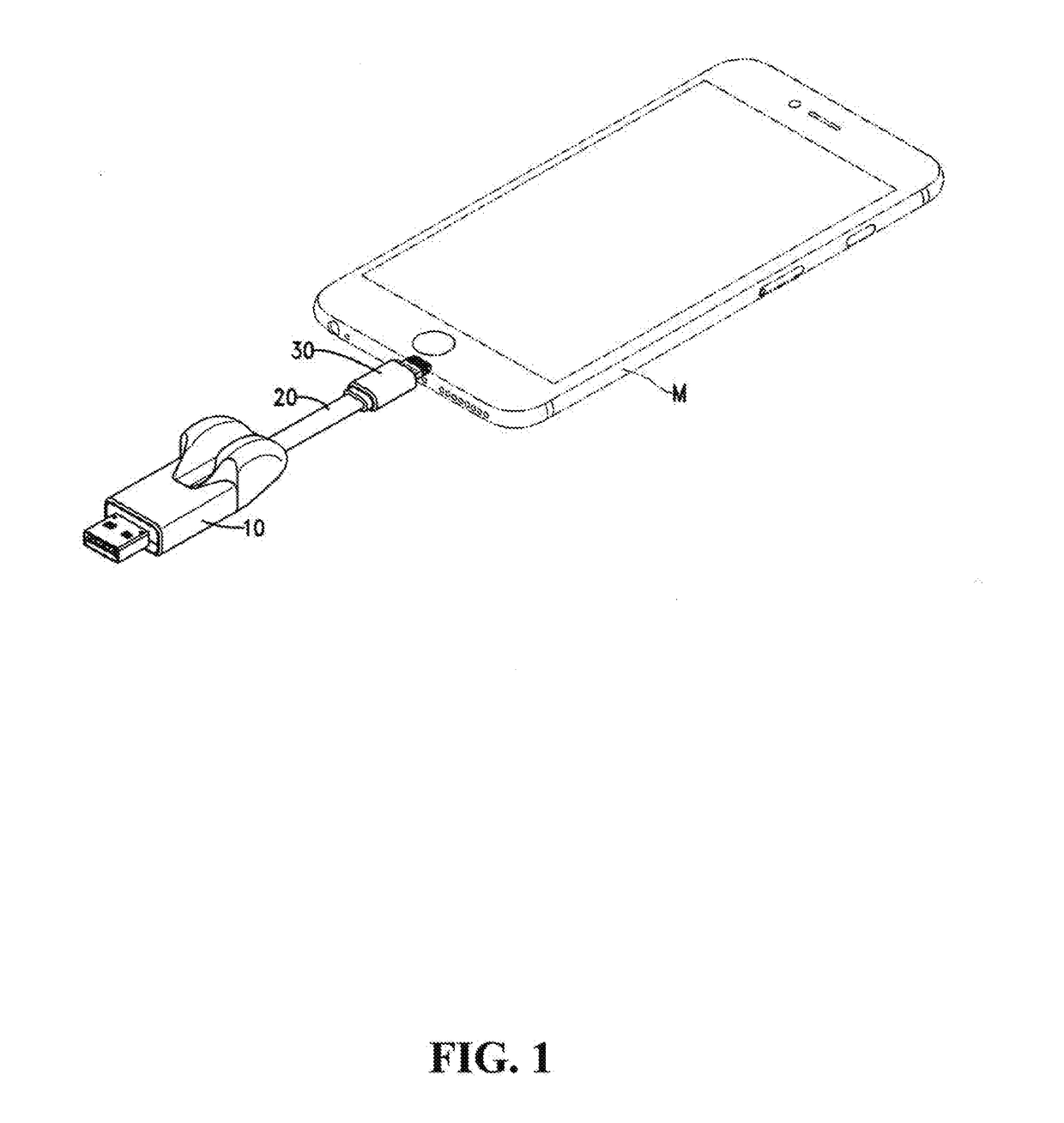
[0028]Please refer to FIG. 1. An electronic storage and transmission device of the present invention includes a storage and transmission body 10, a holding base 11, a connecting wire 20 and a transmission connector 30.

[0029]Please refer to FIGS. 2-4. The storage and transmission body 10 has a body connection port 12; specifically, the storage and transmission body 10 is a flash drive.

[0030]The holding base 11 is located at an end portion of the transmission device body 10, and sticks out a top surface of the storage and transmission body 10, the holding base 11 has a receiving slot 110, a fixing portion 111 and an accommodating portion 112; specifically, the holding base 11 is a soft material, such as rubber. In an embodiment, the storage and transmission body 10 and the holding base 11 can be formed in...


PUM


Abstract

A holding structure of an electronic storage and transmission device of the present invention has a storage and transmission body and a holding base. The storage and transmission body connects to a transmission connector through a connecting wire. The holding base has a receiving slot formed on a top surface of the storage and transmission body, and the transmission connector can be fixed in the receiving slot. Due to only an end portion of the connecting wire fixed on the holding base, the connecting wire can be fully expanded, operation freedom and connection angle are thereby increased; and by disposing the holding base, the transmission connector can be directly fixed in the holding base, so that a folded volume of the electronic storage and transmission device is reduced. Additionally, the electronic storage and transmission device can have functions of storing data and charging electronic devices at the same time.

Description

CROSS-REFERENCE TO RELATED APPLICATION[0001]This application claims the priority of Taiwanese patent application No. 104220531, filed on Dec. 22, 2015, which is incorporated herewith by reference.FIELD OF THE INVENTION[0002]The present invention relates to an electronic storage and transmission device, especially to an electronic storage and transmission having a holding base.BACKGROUND OF THE INVENTION[0003]1. Field of the Invention[0004]The line-type flash drive is an electronic storage and transmission device, which can not only be a memory storage device easy to carry, but also a charging and data transmitting media for electronic products such as smartphones or tablets.[0005]2. The Prior Arts[0006]Please refer to FIG. 5. The line-type flash drive of current technology has a storage and transmission body 40, a connecting wire 50 and a transmission connector 60. The storage and transmission body 40 is a flash drive, so it can be as a memory storage device, and an end portion of t...

Claims


Application Information

Patent Timeline
IPC IPC(8): H05K5/02H01R24/28H01R24/60
CPCH05K5/0278H01R24/60H01R2107/00H05K5/0217H05K5/0247H01R24/28H01R13/72H01R24/62H01R31/065
Inventor WANG, WARREN
Owner PHOTOFAST COMPANY
Why Eureka
Try Eureka