Ultrasound imaging apparatus

Active Publication Date: 2017-06-29
KONINKLJIJKE PHILIPS NV
View PDF1 Cites 6 Cited by
  • Summary
  • Abstract
  • Description
  • Claims
  • Application Information

AI Technical Summary

Benefits of technology

[0034]In a preferred embodiment, the confidence values are determined on the basis of predetermined reference values of the different regions of the object. This is a possibility to determine the confidence values with low technical effort, since the values are predefined in the values can be determined e.g. on the basis of experience values for regions of high and/or low confidence levels.
[0035]In a preferred embodiment, the confidence values are determined on the basis of a propagation model of the anatomical object for the ultrasound waves. This is a possibility to consider the physics of the ultrasound propagation in the tissue of the object so that the confidence values can be determined with high precision.
[0036]In a preferred embodiment, one confidence value is assigned to each voxel of the ultrasound data and the confidence values are stored in a confidence map. This is a possibility to link the voxels of the ultrasound data sets with an individual confidence value so that a calculation of the voxel data and the confidence data can be easily processed.
[0037]In a preferred embodiment, the compound image is generated on the basis of the confidence values, wherein the ultrasound data of the different regions in the different ultrasound data sets are weighted on the basis of the different confidence values to form the compound image. This is a possibility to improve the quality of the compound image, since the ultrasound data of low confidence regions are less considered and the ultrasound data of the regions having a high confidence level are considered more.
[0038]In a preferred embodiment, the image generation unit is adapted to provide a graphical representation of the confidence values withi

Problems solved by technology

However, the known ultrasound imaging systems cannot reflect the anatomical structures of all regions within the field of view

Method used


Image

  • Ultrasound imaging apparatus
  • Ultrasound imaging apparatus
  • Ultrasound imaging apparatus

Examples


Example

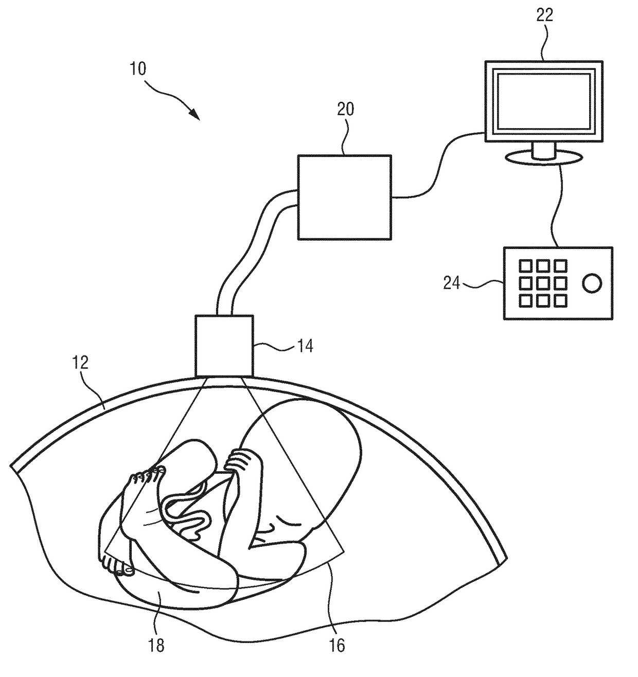
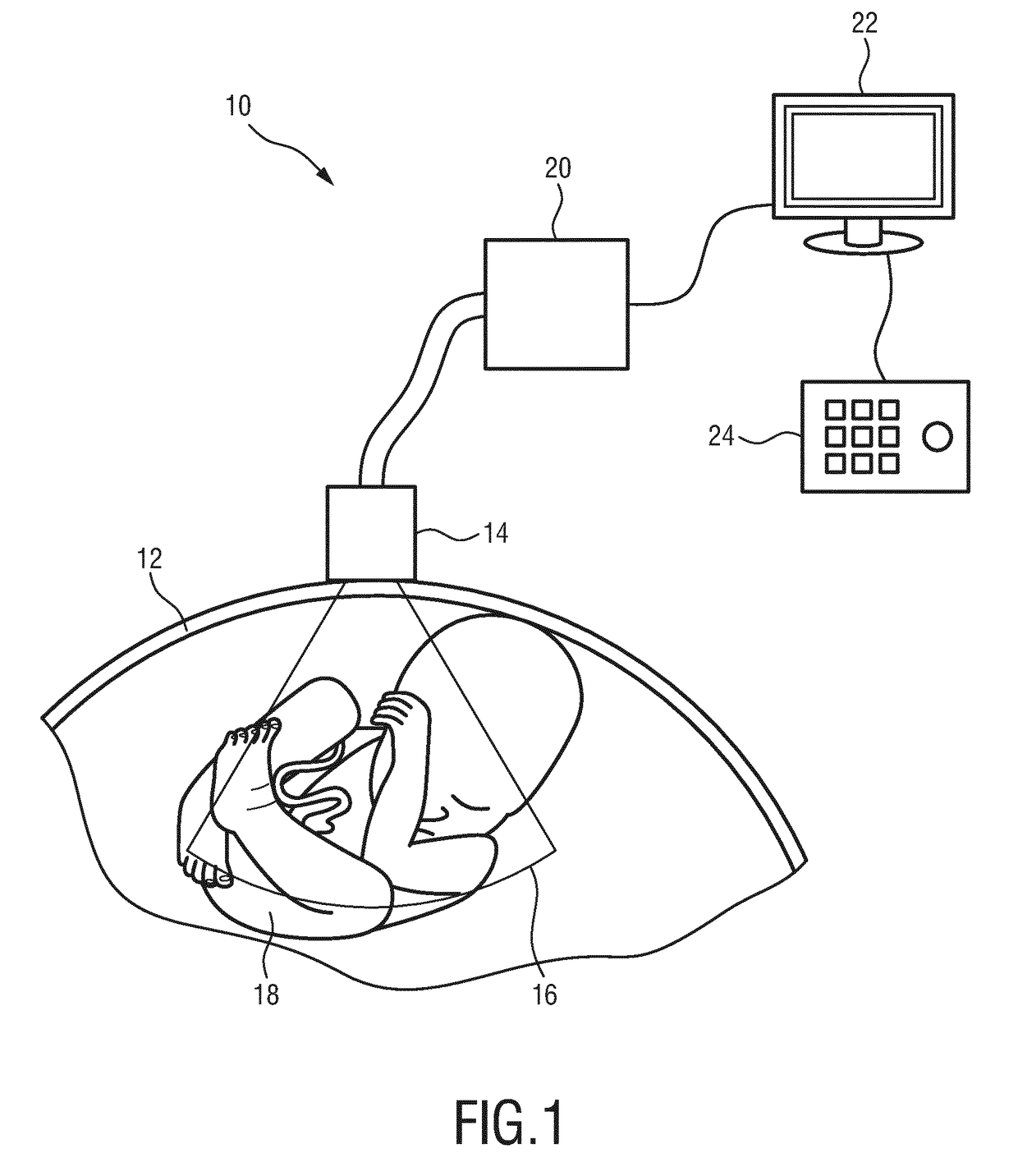
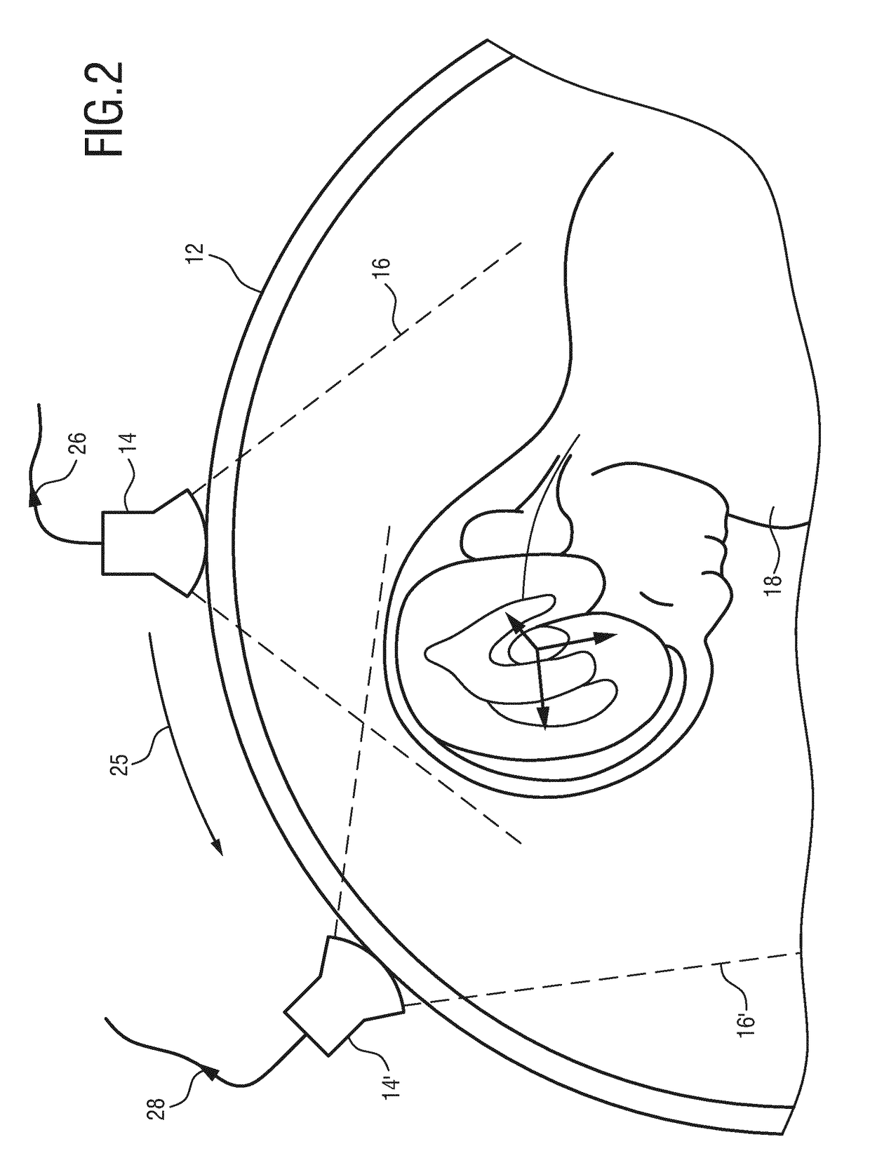
[0048]FIG. 1 shows a schematic illustration of an ultrasound imaging system according to an embodiment generally denoted by 10. The ultrasound imaging system 10 is applied to inspect a volume of an anatomical site, in particular an anatomical site of a patient 12. The ultrasound imaging system 10 comprises an ultrasound probe 14 having at least one transducer array having a multitude of transducer elements for transmitting and / or receiving ultrasound waves. The transducer elements are preferably arranged in a two-dimensional array, in particular for providing a multi-planar or three-dimensional image. The probe 14 is adapted to transmit ultrasound waves in a particular direction and to receive ultrasound waves from a particular direction which forms a field of view 16 of the ultrasound probe 14.

[0049]In the embodiment shown in FIG. 1, the patient 12 is a pregnant person, wherein an anatomical object to be inspected is a foetus 18, which is disposed in the field of view 16.

[0050]Due ...


PUM


Abstract

An ultrasound imaging apparatus (20) is disclosed, comprising a data interface (30) configured to receive a plurality of different ultrasound data sets (26, 28) resulting from an ultrasound scan of an object (18) in different viewing directions. The ultrasound imaging apparatus further comprises a segmentation unit (32) for segmenting anatomical structures of the object in the different ultrasound data sets and for providing segmentation data of the anatomical structures, and a reference determining unit (34) for determining a spatial reference (48, 50, 52, 54) for the different ultrasound data sets on the basis of the segmentation data. A confidence determining unit (40) is included for determining confidence values (56) for different regions of the received ultrasound data on the basis of the spatial reference.

Description

FIELD OF THE INVENTION[0001]The present invention relates to an ultrasound imaging apparatus. An exemplary technical application of the present invention is the generation of two-dimensional images of a foetal skull based on one or more acquired three-dimensional ultrasound scans. The present invention further relates to an ultrasound imaging system for determining ultrasound image data from an object. The present invention further relates to a method for evaluating ultrasound image data from an anatomical site of an object and finally to a computer program comprising program code means for causing a computer to carry out a method for evaluating ultrasound image data from an anatomical site of an object.BACKGROUND OF THE INVENTION[0002]Ultrasound imaging systems are generally known for examination of anatomical features in human patients. In particular, ultrasound imaging systems are used for prenatal screening examination of the foetal central nervous system. A corresponding ultras...

Claims


Application Information

Patent Timeline
IPC IPC(8): A61B8/08G01S7/52G01S15/89A61B8/00
CPCA61B8/5246A61B8/4444A61B8/461A61B8/5207A61B8/0866A61B8/483G01S15/8995A61B8/54G01S7/52071G01S7/52074G01S15/8925G01S15/8936G01S15/8993A61B8/5269A61B8/5253A61B8/145
Inventor ARDON, ROBERTO JOSECUINGNET, REMI NICOLAS THIERRYROUET, JEAN-MICHEL
Owner KONINKLJIJKE PHILIPS NV
Why Eureka
Try Eureka