Pneumatic tire

a technology of pneumatic tires and tires, applied in the field of pneumatic tires, can solve the problems of abnormal abrasion, reduced stiffness of the entire tread block, increased stiffness etc., and achieve the effects of reducing the resonance noise of the tire, reducing the movement of the tread block, and increasing traction for

Active Publication Date: 2017-06-29
KUMHO TIRE CO INC
View PDF0 Cites 6 Cited by
  • Summary
  • Abstract
  • Description
  • Claims
  • Application Information

AI Technical Summary

Benefits of technology

[0012]In consideration of the above-described problems, it is an object of the present invention to provide a pneumatic tire which may minimize a movement of a tire tread block due to a stress generated during contacting with a ground, by changing a shape of a sipe formed in the tread block to increase a traction force, and in particular, may allow for easy manufacture of a tire, improve soil drainage, and increase the traction force in the latter half of a tire lifespan.
[0027]According to the pneumatic tire of the present invention, the three-dimensional inclined surface groove is formed at the upper portion of the sipe formed in the tread block, such that the three-dimensional inclined surface protrusions and the inclined surface grooves respectively formed on both sipe side wall surfaces forming the sipe so as to correspond to each other may minimize the movement of the tread blocks due to the stress generated from the tire contacting with the ground during driving, thus to increase a traction force.
[0028]In addition, according to the pneumatic tire of the present invention, the lower through groove is formed at the lower portion of the sipe formed in the tread block, such that it is possible to reduce a resonance noise of the tire occurring when driving, more easily and automatically discharge the foreign matters caught in the sipes of the tire during driving, and improve the traction performance of the tire in the latter half of the tire lifespan by dividing the remaining tread block after the upper portion of the tread block is worn.
[0029]Further, according to the pneumatic tire of the present invention, the discharge grooves are formed on both inclined surfaces in the width direction of the tread block of the inclined surface protrusion formed on the both sipe side wall surfaces of the tread block forming the three-dimensional inclined surface groove of the sipe along the thickness direction of the tread block, such that it is possible to more effectively prevent the foreign matters from being caught in the sipe together with the above-described lower through groove.

Problems solved by technology

However, when applying the sipes to the tread block for dispersing the stress, an entire stiffness of the tread block is decreased, thereby causing a problem such as abnormal abrasion.
In addition, as a cross-sectional shape of the sipe is complicated, the stiffness of the tread block is increased, but it is difficult to manufacture the tire.
Further, the sipe has a structure that, when soil enters into the sipe, it is difficult to discharge the soil, thus the introduced soil is accumulated in the sipe, and the sipe is clogged.
When becoming the tire in the latter half of use, a depth of the sipe of the tread block is decreased, such that there is a problem of reducing the traction force.

Method used


Image

  • Pneumatic tire
  • Pneumatic tire
  • Pneumatic tire

Examples


Embodiment Construction

[0037]Hereinafter, preferred embodiments of the present invention will be described in detail with reference to the accompanying drawings, so as to assist those having ordinary skill in the art in a comprehensive understanding of the invention, and the present invention is not limited to the embodiments disclosed below. In the embodiments of the present invention, publicly known functions and configurations that are judged to be able to make the purport of the present invention unnecessarily obscure will not be described. Referring to the drawings, wherein like reference characters designate like or corresponding parts throughout the several views.

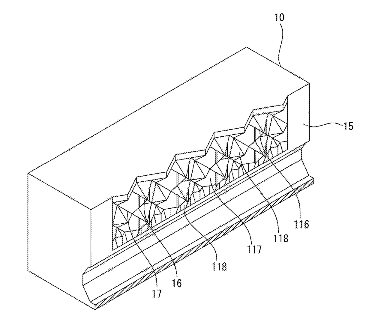
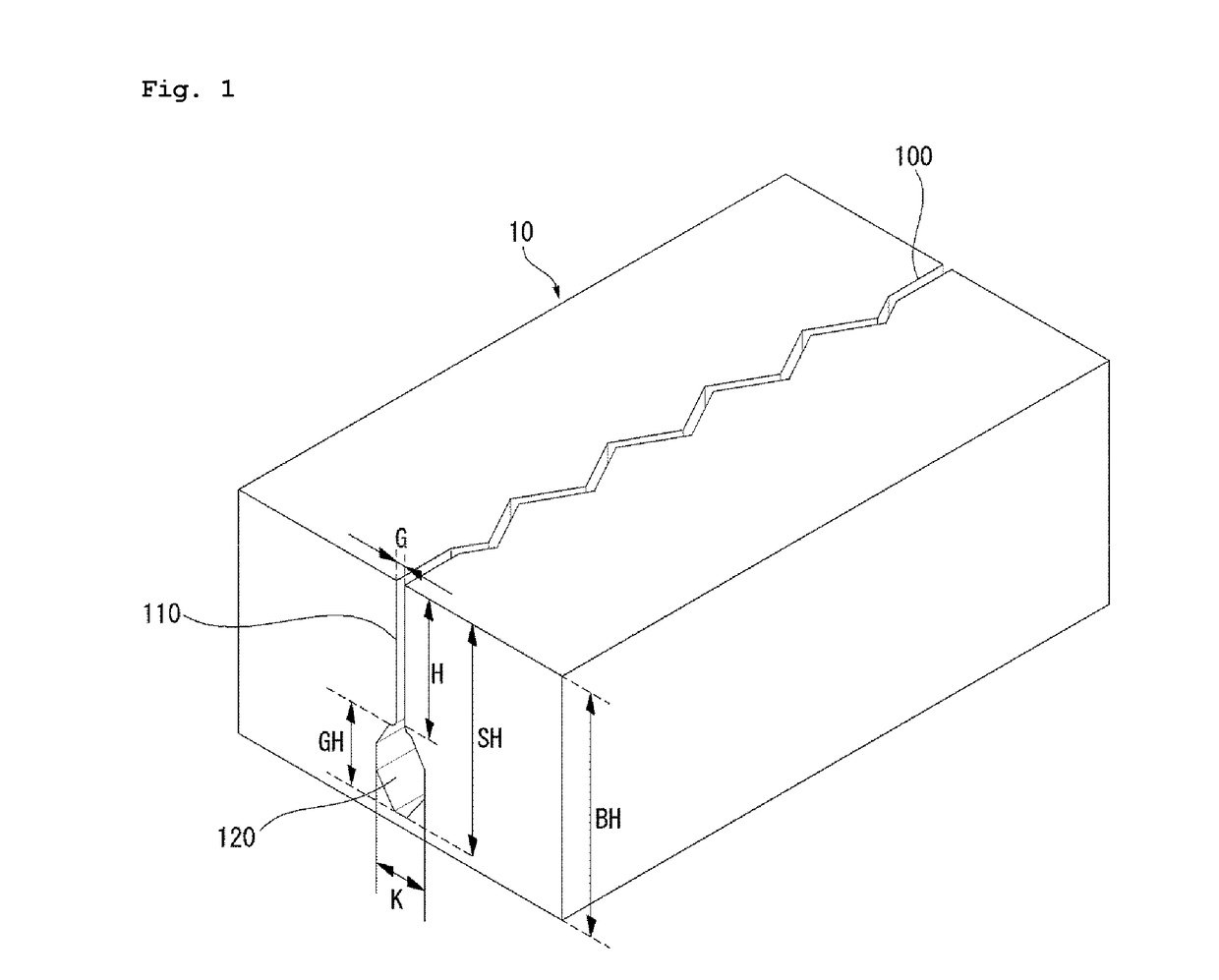
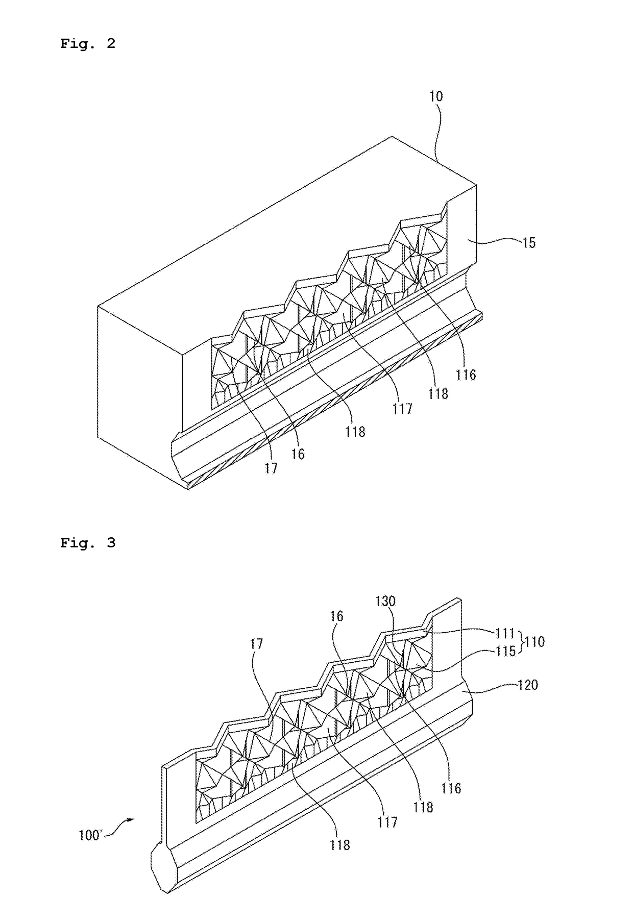
[0038]FIG. 1 is a perspective view illustrating a tread block applied to a pneumatic tire according to an embodiment of the present invention, FIG. 2 is a partially cutaway view of the tread block taken on a sipe of FIG. 1, and FIG. 3 is a perspective view illustrating a sipe blade of FIG. 2.

[0039]Referring to FIGS. 1 and 2, the pneumatic ...


PUM

PropertyMeasurementUnit
thicknessaaaaaaaaaa
thicknessaaaaaaaaaa
widthaaaaaaaaaa

Abstract

The present invention provides a pneumatic tire including a tread block 10 having a sipe 100 formed therein. A three-dimensional inclined surface groove 110 is formed at an upper portion of the sipe 100 formed in the tread block 10, such that three-dimensional inclined surface protrusions 16 and inclined surface grooves 17 respectively formed on both sipe side wall surfaces 15 forming the sipe 100 so as to correspond to each other may minimize a movement of the tread blocks 10 due to a stress generated from the tire contacting with a ground during driving, so as to increase a traction force. In addition, a lower through groove is formed at a lower portion of the sipe 100 formed in the tread block 10, such that it is possible to reduce a resonance noise of the tire occurring when driving, more easily and automatically discharge the foreign matters caught in the sipes 100 of the tire during driving, and improve a traction performance of the tire in the latter half of the tire lifespan by dividing the remaining tread block 10 after the upper portion of the tread block 10 is worn.

Description

CROSS REFERENCE TO RELATED APPLICATIONS[0001]This application claims priority to Korean Patent Application No. 10-2015-0188571, filed on Dec. 29, 2015 in the Korean Intellectual Property Office, the entire disclosure of which is incorporated herein by reference.BACKGROUND OF THE INVENTION[0002]Field of the Invention[0003]The present invention relates to a pneumatic tire, and more particularly, to a pneumatic tire having sipes which may minimize a movement of a tire tread block due to a stress generated during contacting with a ground, improve soil drainage, and increase a traction force in the latter half of use.[0004]Description of the Related Art[0005]As is generally known, a tread surface of a tire of an automobile, which contacts with a ground, includes grooves formed therein, and tread blocks which are defined by the grooves and formed thereon while having a constant tread pattern.[0006]In order to improve a traction force and a braking force, the sipes are formed in the tread ...

Claims


Application Information

Patent Timeline
Patent Type & Authority Applications(United States)
IPC IPC(8): B60C11/12B60C11/03
CPCB60C11/1218B60C11/0323B60C11/1272B60C11/1259B60C11/1204B60C11/13B29D2030/0613B60C11/1281
Inventor LEE, JONG SEOSEO, HYUNG-JU
Owner KUMHO TIRE CO INC
Why Eureka
Try Eureka